Leakage repairing rod for stopping slurry leakage of cast-in-situ bored pile on riprap embankment in complex sea area

A technology for drilling cast-in-place piles and leak repair, which is applied in the field of leak repair rods, can solve the problems of difficult control, leakage of slurry in the deep coarse sand layer, and poor leakage plugging effect, and achieves the effect of simple operation.

Pending Publication Date: 2022-07-29
中交二航局第一工程有限公司 +1
View PDF1 Cites 0 Cited by
  • Summary
  • Abstract
  • Description
  • Claims
  • Application Information

AI Technical Summary

Problems solved by technology

[0005] The main purpose of the present invention is to provide a repair rod for preventing grout leakage of bored piles on riprap embankments in complex sea areas, so as to solve

Method used


Image

  • Leakage repairing rod for stopping slurry leakage of cast-in-situ bored pile on riprap embankment in complex sea area
  • Leakage repairing rod for stopping slurry leakage of cast-in-situ bored pile on riprap embankment in complex sea area
  • Leakage repairing rod for stopping slurry leakage of cast-in-situ bored pile on riprap embankment in complex sea area

Examples


Example Embodiment

[0022] Example 1

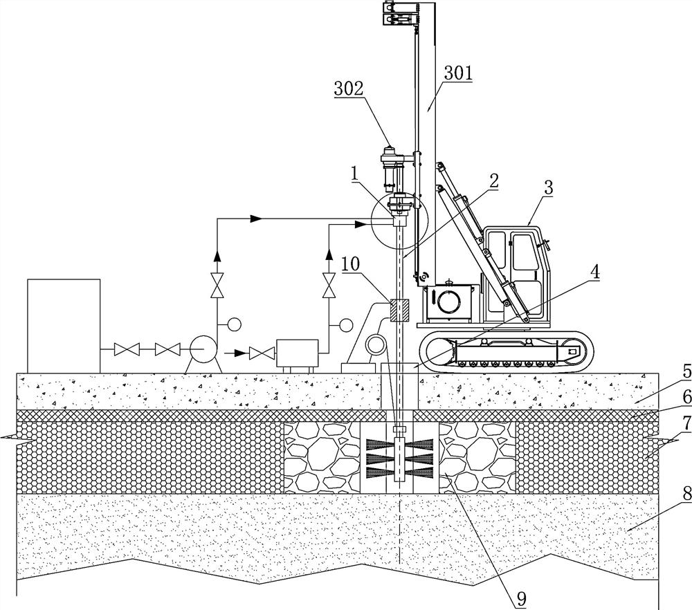
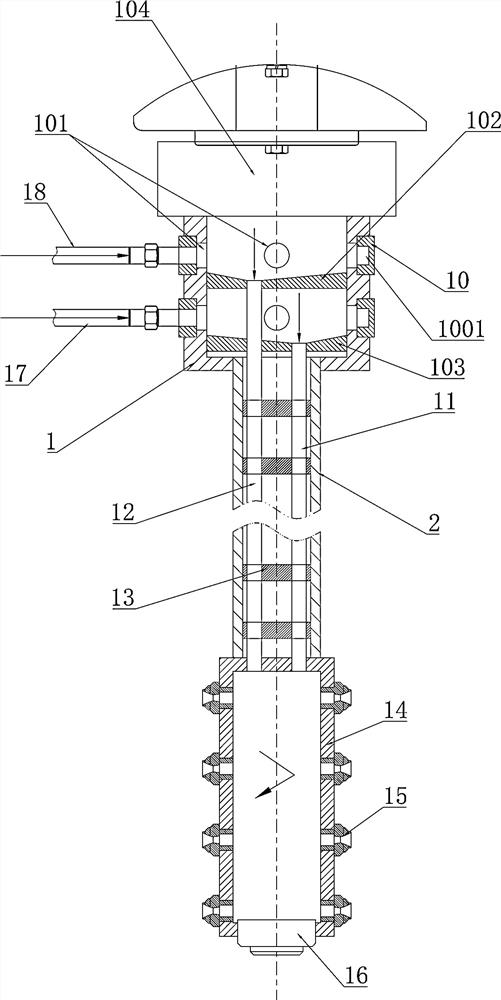
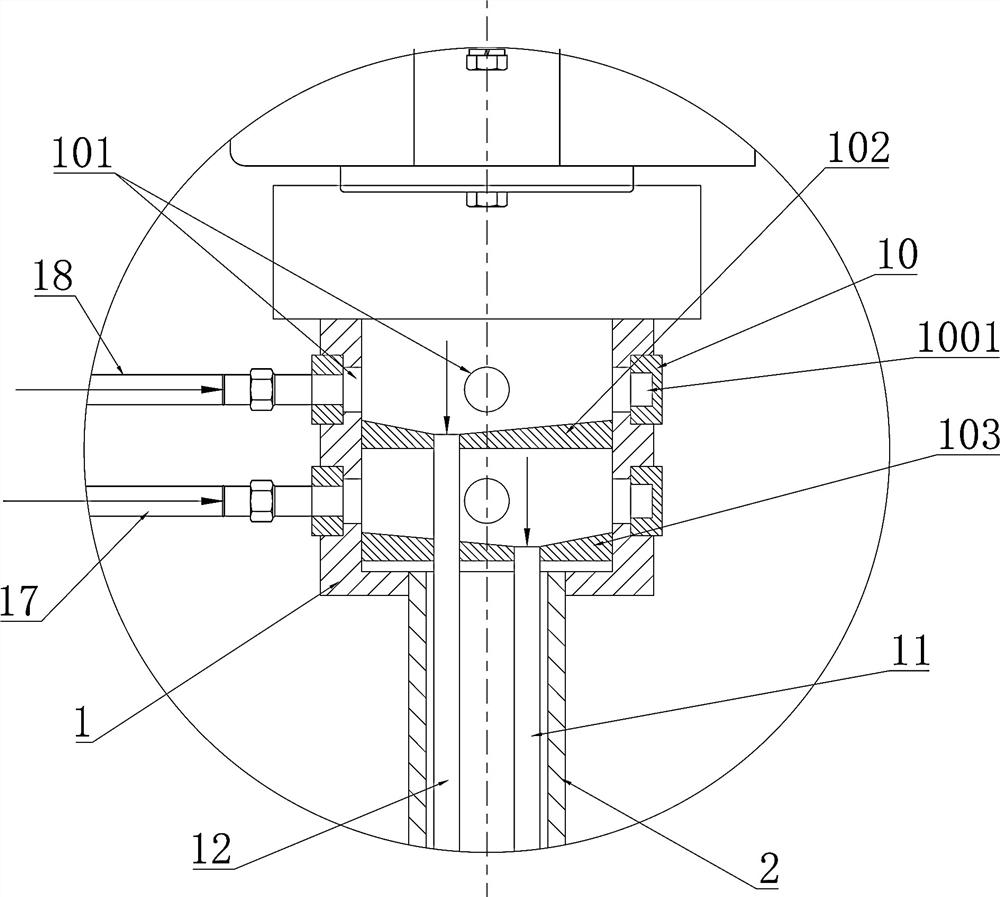
[0023] like Figures 1~4 As shown in the figure, a leakage repair rod used for the leakage of grouting of bored piles on riprap embankments in complex sea areas is provided. A plurality of nozzles 15, the grouting rotating ring 1 at the upper end of the leak repair rod 2 is connected to the driving rotating seat 302 of the bolting rig 3, the air pressure pipe 17 and the grouting pipe 18 are respectively connected with the grouting rotating ring 1, and the air pressure pipe 17 and the injection pipe are respectively connected. The slurry pipe 18 is in rotational sealing communication with the grouting rotary ring 1 , and the leak repair rod 2 is provided with an air pressure standpipe 11 and a solution standpipe 12 . The air pressure pipeline 17 and the grouting pipeline 18 are connected to the inside of the grouting rotary ring 1 . The gas injection pipeline 17 and the grouting pipeline 18 are merged into the grouting rotary ring 1 , and the grouting rotar...

Example Embodiment

[0031] Example 2

[0032] Further illustrate in conjunction with embodiment 1, as Figure 1-4 As shown, the bolt on the bolt drilling rig 3 is disassembled from the driving rotating base 302 , and the leak trap 2 is installed on the rotating base 302 of the bolt drilling rig 3 , and the rotating base 302 can slide up and down on the sliding table 801 .

[0033] The bolting rig 3 extends the leakage repair rod 2 through the steel casing 12 to the slurry leakage position.

[0034] The position of the spray seat 14 at the lower end of the leak trap 2 is adjusted by sliding the rotating seat 302 on the sliding table 301 by the driving of the bolt drilling machine 3 .

[0035] After the position of the nozzle seat 14 is adjusted accurately, the grouting pump and the air compressor are turned on, and the slurry is mixed with the air to form a strong impact force.

[0036] Mix cement (PC42.5) and quick-setting agent in the dispensing container, the water-cement ratio is 1:1, the ce...


PUM


Abstract

The invention provides a leak repairing rod for stopping slurry leakage of a cast-in-situ bored pile on a riprap embankment in a complex sea area, a grouting rotating ring is arranged at one end of the leak repairing rod, a spraying seat is arranged at the other end of the leak repairing rod, a plurality of spraying heads are arranged on the spraying seat, and the grouting rotating ring at the upper end of the leak repairing rod is connected with a driving rotating seat of a jumbolter. The air pressure pipeline and the grouting pipeline are communicated with the grouting rotating ring respectively and are rotatably and hermetically communicated with the grouting rotating ring, an air pressure vertical pipe and a solution vertical pipe are arranged in the leak repairing rod, the air pressure vertical pipe is communicated with the air pressure pipeline, and the solution vertical pipe is communicated with the grouting pipeline. Air and leaking stoppage slurry are accurately sprayed to the leakage position through the parallel pipelines, the leaking stoppage slurry forms a strong and hard hole wall through chemical reaction, and therefore the purpose of leaking stoppage is achieved. The equipment for quickly stopping the leakage of the cast-in-situ bored pile slurry on the riprap embankment in the complex sea area is simple to operate and accurate in leakage repairing.

Description

technical field [0001] The invention relates to the technical field of pile foundation construction, in particular to a leakage repair rod used for slurry leakage and slurry leakage prevention of bored piles on riprap embankments in complex sea areas. Background technique [0002] During the construction of bored piles on riprap embankments in complex sea areas, when passing through the rock layer, medium-coarse sand layer, and gravel layer, problems such as slurry leakage and hole collapse are very likely to occur, and the environmental protection requirements are high. Preventing mud spillage is also a key difficulty. [0003] The leakage of slurry in the deep coarse sand layer is extremely difficult to control and the plugging effect is not good, resulting in the failure of piling, which brings great economic losses to the enterprise and society and requires a lot of remedial measures. [0004] Chinese patent CN101173516B "Grouting Curtain Method for Preventing Slurry Le...

Claims


Application Information

Patent Timeline
IPC IPC(8): E02D5/34E02D5/64E02D15/04
CPCE02D5/34E02D5/64E02D15/04E02D2250/003
Inventor 邹红霞谭永安李子侠余杨明李娜邓龙照谢鹏许环智
Owner 中交二航局第一工程有限公司
Why Eureka
Try Eureka