Backfill compaction device for narrow area of foundation pit

A compaction device and backfill technology, which is applied in soil protection, infrastructure engineering, earth movers/shovels, etc. It can solve the problem of gaps that cannot be eliminated, large gaps, and the lack of use value of backfill compaction devices, etc. problems, to achieve the effect of improving the use value and ensuring the compaction effect

Active Publication Date: 2022-07-29
YUEQING CONSTR SUPERVISION CO LTD
View PDF7 Cites 2 Cited by
  • Summary
  • Abstract
  • Description
  • Claims
  • Application Information

AI Technical Summary

Problems solved by technology

[0003] In the existing building construction process, it is necessary to fill the narrow area of ​​the foundation pit. After filling, it needs to be compacted by a compaction device. However, for the narrow area of ​​the foundation pit, a large compaction device cannot be put into use. It is operated through a miniature compaction device. When the existing miniature compaction device is performing backfill compaction operations, the hydraulic cylinder drives the pressure plate to squeeze the backfill soil. During the filling process, part of the backfill soil has a large volume. After the backfill soil is filled, there are large voids around it, and this part of the gap cannot be eliminated under a single extrusion operation. As a result, after the backfill soil is compacted, there are voids inside, and the strength of the narrow area of ​​the foundation pit after filling cannot reach To the specified standard, resulting in the lack of use value of the backfill compaction device

Method used


Image

  • Backfill compaction device for narrow area of foundation pit
  • Backfill compaction device for narrow area of foundation pit
  • Backfill compaction device for narrow area of foundation pit

Examples


Embodiment Construction

[0029] The technical solutions in the embodiments of the present invention will be clearly and completely described below with reference to the accompanying drawings in the embodiments of the present invention. Obviously, the described embodiments are only a part of the embodiments of the present invention, but not all of the embodiments.

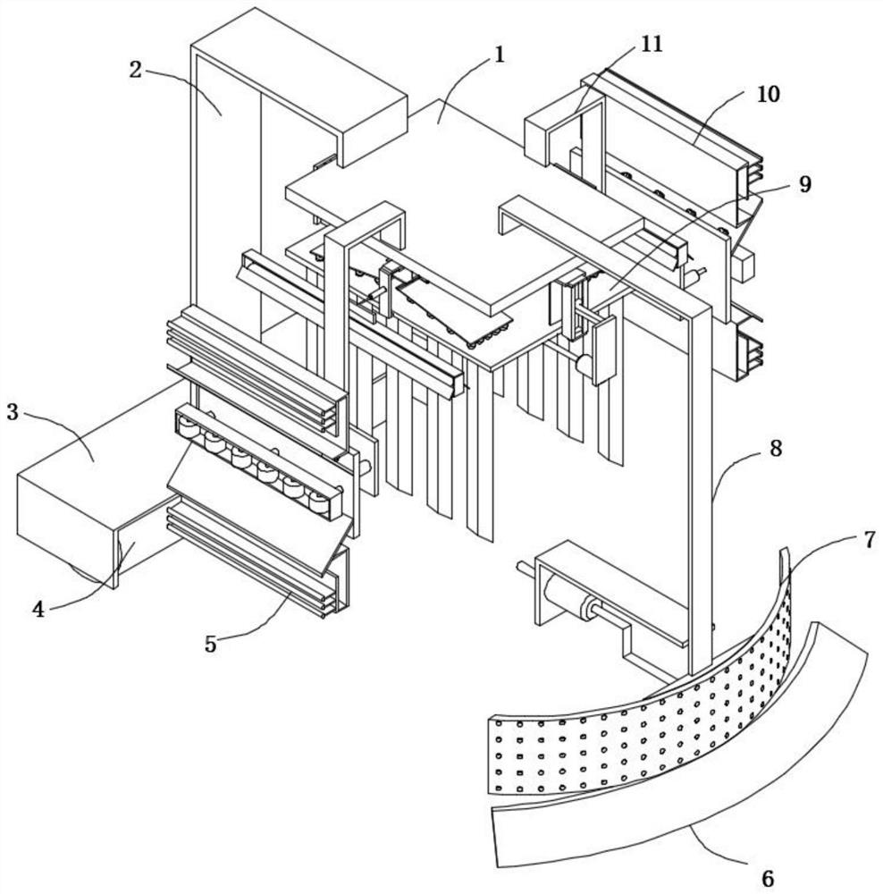
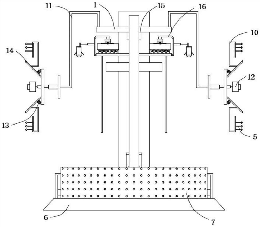
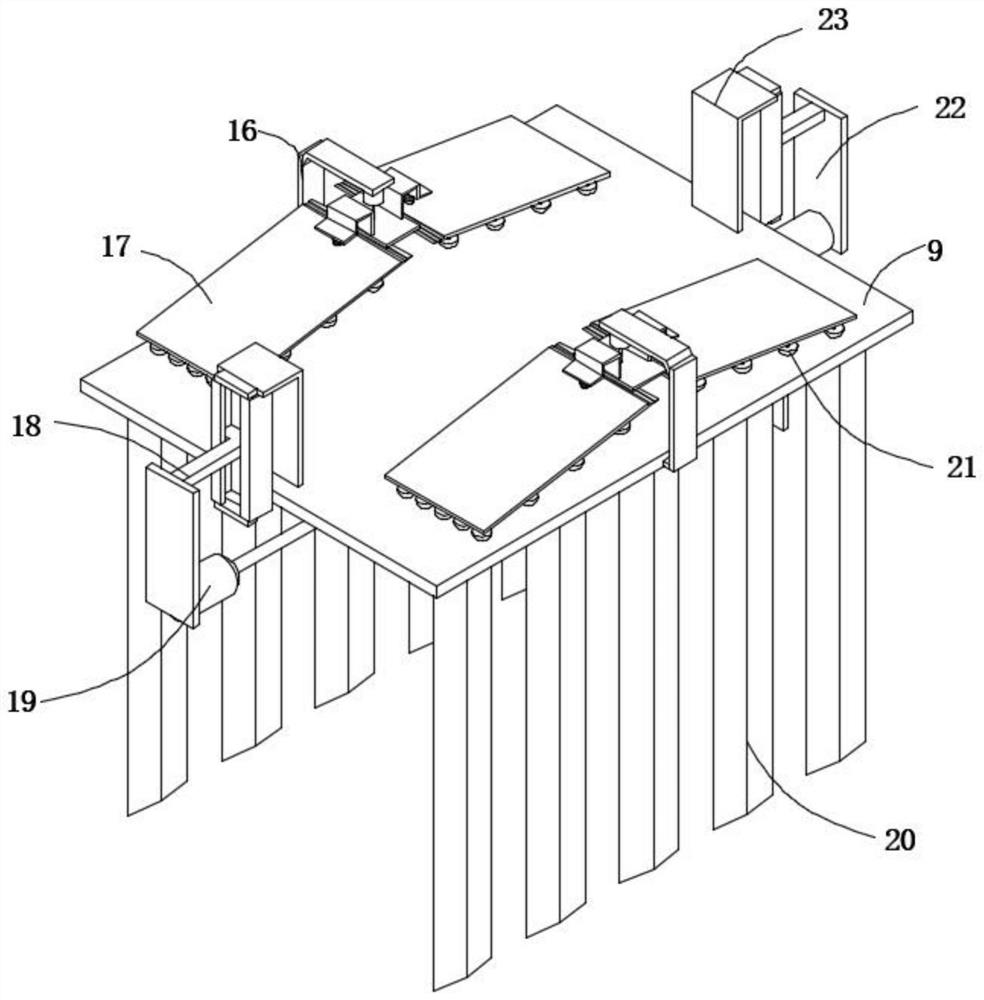
[0030] refer to Figure 1-5, a compacting device for backfilling soil in a narrow area of ​​a foundation pit, comprising a mounting plate 1, a cylinder 15 is fixedly connected to the bottom outer wall of the mounting plate 1, and a pressure plate 9 is fixedly connected to the bottom outer wall of the cylinder 15, and both ends of the bottom outer wall of the pressure plate 9 are equal A vibrating plate 20 is fixedly connected at a distance, and both ends of the top outer wall of the pressing plate 9 are provided with a vibrating mechanism, and both outer walls of the pressing plate 9 are provided with a smoothing mechanism. The vibrating mec...


PUM


Abstract

The invention belongs to the technical field of building construction, and particularly relates to a foundation pit narrow area backfill compaction device which comprises a mounting plate, an air cylinder is fixedly connected to the outer wall of the bottom of the mounting plate, and a pressing plate is fixedly connected to the outer wall of the bottom of the air cylinder. According to the device, the anti-protrusion assembly is arranged, when the compaction assembly is used for compacting backfill soil, the backfill soil on the outer side of a pressing plate is prone to being extruded and protruding along with extrusion between the pressing plate and the backfill soil, and a third hydraulic cylinder is adjusted to drive a pushing plate to move; according to the backfilled soil compacting device, the pushing plate is arranged on the backfilled soil compacting device, so that the flattening roller below the pushing plate extrudes and flattens the bulged backfilled soil, the situation that the compaction position is hollow due to the bulged backfilled soil is prevented, the backfilled soil compacting effect is further improved, and in the extruding and flattening process of the flattening roller, the protection pieces at the two ends of the roller frame protect the flattening roller; and the condition that the smoothing roller rotates to drive the backfill soil to rise is prevented, and backfill soil backflow is avoided.

Description

technical field [0001] The invention relates to the technical field of building construction, in particular to a compaction device for backfilling soil in a narrow area of ​​a foundation pit. Background technique [0002] The foundation pit is a soil pit excavated at the base design position according to the base elevation and the base plane size; before excavation, the excavation plan should be determined according to the geological and hydrological data and the conditions of the buildings near the site, and waterproof and drainage work should be done. If the excavation is not deep, the method of placing the side slope can be used to stabilize the soil slope, and the size of the slope shall be determined according to the relevant construction engineering regulations; if the excavation is deeper and there are adjacent buildings, the foundation pit wall support method and the shotcrete wall protection method can be used. Large-scale foundation pits even use methods such as un...

Claims


Application Information

Patent Timeline
Patent Type & Authority Applications(China)
IPC IPC(8): E02F5/22E02D3/00E02D3/054
CPCE02F5/223E02D3/00E02D3/054
Inventor 陈永海瞿维福林叶宇
Owner YUEQING CONSTR SUPERVISION CO LTD
Why Eureka
Try Eureka