
Battery production device and battery production method

A technology for preparing devices and batteries, which is applied in the manufacture of electrolyte batteries, secondary batteries, non-aqueous electrolyte batteries, etc., can solve the problems of short circuits, affecting the quality of finished products, and high production costs

Active Publication Date: 2021-04-20
CHINA FIRST AUTOMOBILE
View PDF13 Cites 0 Cited by
  • Summary
  • Abstract
  • Description
  • Claims
  • Application Information

AI Technical Summary

Problems solved by technology

[0004] First of all, because the electrical signal needs to be introduced into the glove box, it is necessary to preset or modify the electrical circuit of the glove box, which brings a lot of inconvenience, difficult processing, and high production cost.
[0005] Secondly, it is necessary to provide a certain accommodation space for the tablet press in the glove box, which is easy to cause space waste
Due to the occupancy of the glove box by the tablet press, when analyzing multiple samples or multiple conditions, for example, experiments under different charging and discharging systems for multiple samples, the multi-channel function of the battery charging and discharging instrument cannot be well utilized. It can only be carried out sequentially, which consumes too much time and greatly reduces the test efficiency
[0006] Thirdly, the battery is easily affected by the outside world, causing short circuit, open circuit, etc., which will affect the quality of the finished product

Method used


Image

  • Battery production device and battery production method
  • Battery production device and battery production method
  • Battery production device and battery production method

Examples


Embodiment Construction

[0052] In order to make the technical problems solved by the present invention, the technical solutions adopted and the technical effects achieved clearer, the technical solutions of the embodiments of the present invention will be further described in detail below in conjunction with the accompanying drawings. Obviously, the described embodiments are only the technical solutions of the present invention. Some, but not all, embodiments. Based on the embodiments of the present invention, all other embodiments obtained by those skilled in the art without creative efforts fall within the protection scope of the present invention.

[0053] In the description of the present invention, unless otherwise clearly specified and limited, the terms "connected", "connected" and "fixed" should be understood in a broad sense, for example, it can be a fixed connection, a detachable connection, or an integrated ; It can be a mechanical connection or an electrical connection; it can be a direct...


PUM


Abstract

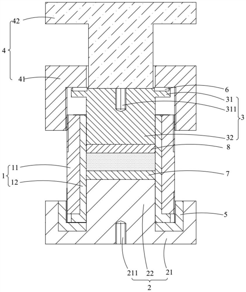
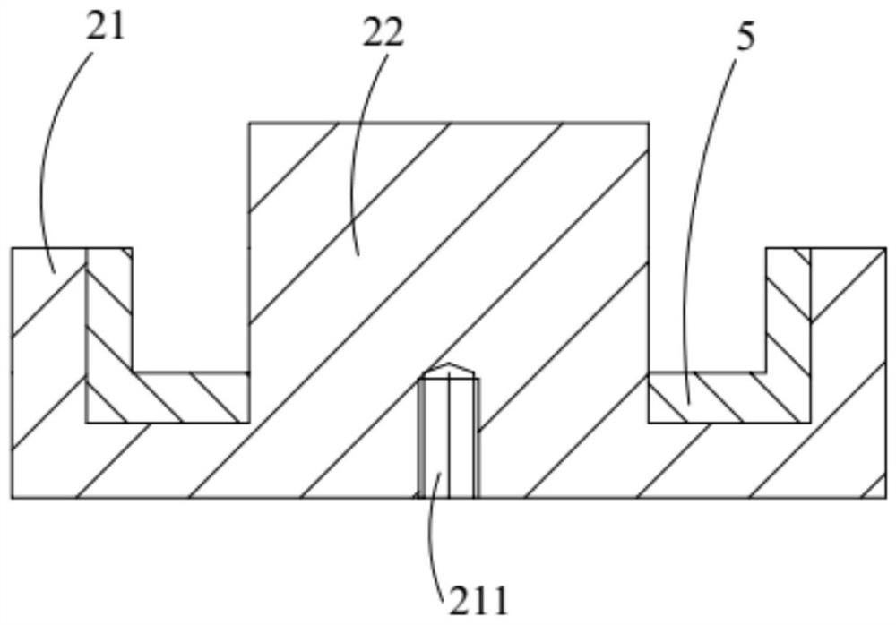
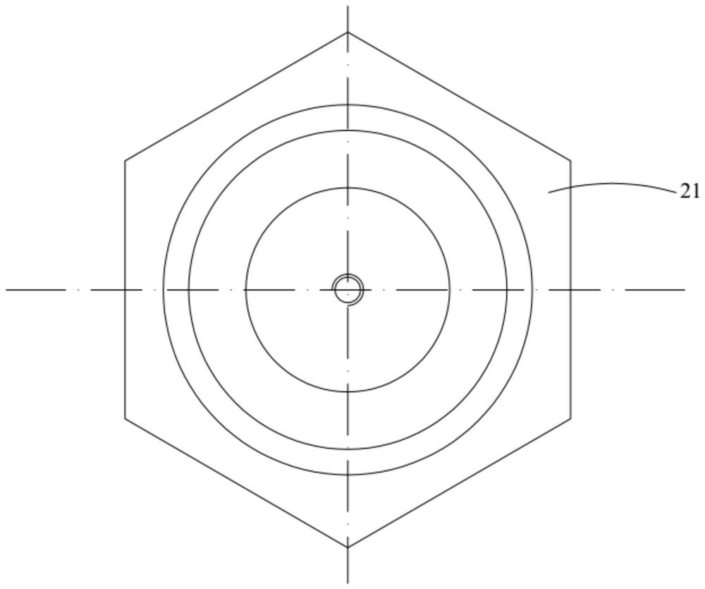
The invention belongs to the technical field of battery production and manufacturing, and discloses a battery production device and a battery production method. The battery production device comprises a feeding assembly, a lower die assembly, an upper die assembly and a pressing assembly, wherein the upper die assembly includes an upper cover and a lower pressing column, the upper cover is arranged above the feeding assembly, the lower pressing column is arranged on the side, close to the feeding assembly, of the upper cover, and the lower pressing column is arranged in the feeding assembly in a penetrating mode; the pressing assembly includes a pressure maintaining piece and a pressure bearing column, the upper end of the pressure bearing column abuts against pressure controllable equipment, the lower end of the pressure bearing column penetrates through the pressure maintaining piece and then abuts against the upper cover, and the pressure controllable equipment drives the upper die assembly to move relative to the feeding assembly through the pressure bearing column so that the lower pressing column can abut against a medium to be crimped; and the pressure maintaining piece is arranged outside the feeding assembly in a sleeving mode and can slide relative to the feeding assembly so that the inner wall of the pressure maintaining piece abuts against the upper cover. The battery production device reduces the production cost and improves the quality of finished products.

Description

technical field [0001] The invention relates to the technical field of battery production and manufacturing, in particular to a battery preparation device and a battery preparation method. Background technique [0002] At present, solid-state batteries use solid-state electrolytes instead of organic liquid electrolytes for production and manufacturing, which not only has good safety, but also has greater room for improvement in terms of specific energy, specific power density, and cycle performance. [0003] Existing solid electrolytes and all-solid-state batteries are usually constructed by powder molding method, so that current collectors, electrodes and electrolytes form a layered structure. Since the positive and negative electrode materials and solid electrolyte materials require an inert gas as a protected closed environment, during electrochemical characterization (such as charge and discharge experiments, AC impedance, cyclic voltammetry, and DC polarization, etc.), ...

Claims


Application Information

Patent Timeline
Patent Type & Authority Applications(China)
IPC IPC(8): H01M10/058H01M10/0562
CPCY02E60/10Y02P70/50
Inventor 翟喜民陈慧明姜涛孙焕丽荣常如胡景博赵光宇闫晟睿孟祥宇
Owner CHINA FIRST AUTOMOBILE
Learn More