Asymmetric reduction and drawing process for large forgings

An asymmetric and reduction technology, applied in the field of forging, can solve problems such as the limitation of large reduction rate, achieve the effect of reducing the limitation of headroom, avoiding multiple flips, and improving product quality

Active Publication Date: 2017-11-07
TIANJIN HEAVY EQUIP ENG RES +1
View PDF3 Cites 0 Cited by
  • Summary
  • Abstract
  • Description
  • Claims
  • Application Information

AI Technical Summary

Problems solved by technology

[0003] In view of the above analysis, the present invention aims to provide an asymmetrical reduction and drawing process for large forgings, which is used to solve the problem of the limitation of the existing large forgings on the large reduction rate. This method does not change the original accessories Under the premise of the reduction rate control, the reduction rate during the drawing process is greatly improved to ensure the hot working quality of large forgings

Method used


Image

  • Asymmetric reduction and drawing process for large forgings
  • Asymmetric reduction and drawing process for large forgings
  • Asymmetric reduction and drawing process for large forgings

Examples


Embodiment 1

[0027] Taking the high and medium pressure rotor forging of a thermal power steam turbine as an example, the diameter is The upsetting forging with a weight of 66t is drawn into a diameter of Finished forgings.

[0028] The KD method was used for elongation, and both the upper and lower anvils were V-shaped anvils, and the width ratio of the anvils was 0.6.

[0029] Adopt 15000T hydraulic press.

[0030] The elongation process is carried out according to the following steps:

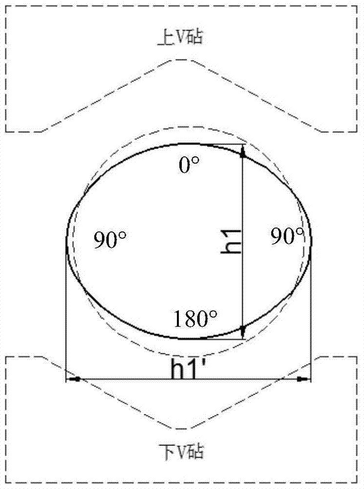
[0031] 1) Put the forgings in accordance with figure 1 Placed in the position shown, the forging is pressed with a small reduction rate in the first pass, and the reduction rate is 15%, and the cross-section of the forging is prefabricated into an ellipse, so as to prevent the forging from being too wide and exceeding the plastic deformation due to the large reduction rate of subsequent multiple passes. scope;

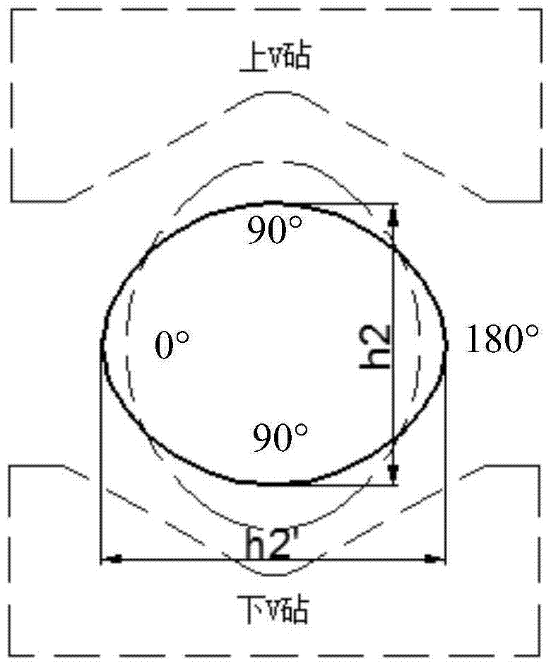
[0032] 2) Turn the forging 90°, such as figure 2 In the position shown, carry out th...

Embodiment 2

[0046] Taking the high and medium pressure rotor forging of a thermal power steam turbine as an example, the diameter is The upsetting forging with a weight of 60t is drawn into a diameter of Finished forgings.

[0047] The KD method was used for elongation, and both the upper and lower anvils were V-shaped anvils, and the width ratio of the anvils was 0.7.

[0048] Adopt 15000T hydraulic press.

[0049] The elongation process is carried out according to the following steps:

[0050] 1) Put the forgings in accordance with figure 1 Placed in the position shown, the forging is pressed with a small reduction rate in the first pass, and the reduction rate is 15%, and the cross-section of the forging is prefabricated into an ellipse, so as to prevent the forging from being too wide and exceeding the plastic deformation due to the large reduction rate of subsequent multiple passes. scope;

[0051] 2) Turn the forging 90°, such as figure 2 In the position shown, carry out th...


PUM


Abstract

The invention relates to a large forging asymmetric rolling reduction drawing-out process, specifically comprising the following steps: (1) performing rolling reduction with a small rolling reduction rate being 13-15% for the first pass; performing rolling reduction with each large rolling reduction rate being 25-35% for the second pass, wherein during rolling reduction of each pass, a forging subjected to the rolling reduction at the last pass is turned by 90 degrees, and a total pass number is not lower than 4; (3) performing rolling reduction by regulating the small rolling reduction rate to enable the forging to achieve a target forging. A center compacting effect of a large forging is realized with a smaller forging rate by optimizing the rolling reduction rate under the premise of not changing an original auxiliary tool, thus improving the internal forging quality of the forging; the forging method can be applied to a forging process of optimizing the large-scale forging, and has important meaning for improving the forging manufacturing efficiency and improving a finished product rate of the large-scale forging.

Description

technical field [0001] The invention relates to the field of forging technology, in particular to an asymmetric reduction and drawing process for large forgings. Background technique [0002] Forging mainly solves the as-cast defects of compacted large steel ingots such as internal looseness, welding holes, and broken coarse grains. The larger the steel ingot, the more serious the segregation of the steel ingot, the more internal defects, and the higher the requirements for forging compaction. When forging, the steel ingot needs a large upsetting ratio and elongation ratio to improve or weld these internal as-cast defects. After the large upsetting ratio is upsetting, if the amount of elongation and reduction is small, the effect of welding the core will not be achieved; if the compaction is directly adopted with a large reduction, the diameter of the forging in the vertical direction will be larger, and the forging will be rotated 90° After 180°, it is often limited by the...

Claims


Application Information

Patent Timeline
Patent Type & Authority Patents(China)
IPC IPC(8): B21J5/06
CPCB21J5/06
Inventor 季雪曹志远
Owner TIANJIN HEAVY EQUIP ENG RES
Why Eureka
Try Eureka