Curved diaphragm for diaphragm compressor

A diaphragm compressor and curved technology, applied in the field of curved diaphragms, can solve the problems of low working displacement and small volume of the membrane cavity, and achieve the effect of increasing the displacement, increasing the volume of the membrane cavity and ensuring the sealing effect.

Active Publication Date: 2022-07-29
CHINA AGRI UNIV
View PDF5 Cites 0 Cited by
  • Summary
  • Abstract
  • Description
  • Claims
  • Application Information

AI Technical Summary

Problems solved by technology

[0003] The purpose of the present invention is to provide a curved diaphragm used in diaphragm compressors to solve the problems of small cavity volume and low working displacement of existing diaphragm compressors

Method used


Image

  • Curved diaphragm for diaphragm compressor
  • Curved diaphragm for diaphragm compressor
  • Curved diaphragm for diaphragm compressor

Examples


Embodiment Construction

[0029] The specific embodiments of the present invention will be further described below with reference to the accompanying drawings.

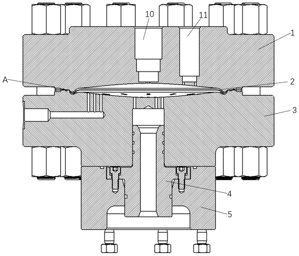
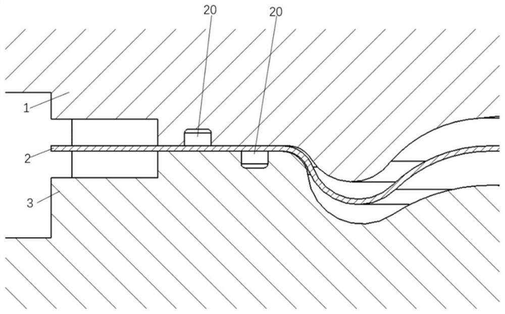
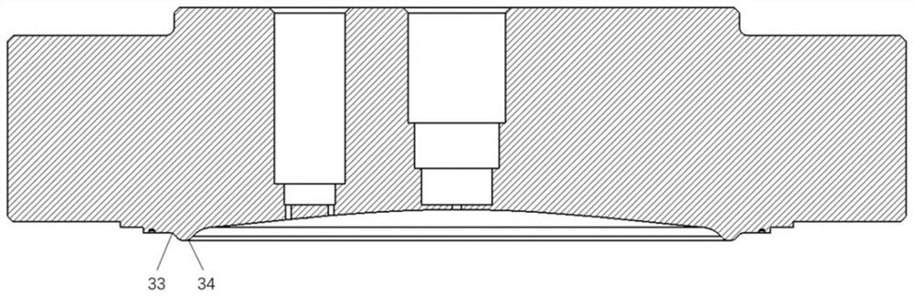
[0030] like Figure 1 to Figure 4 As shown, a curved diaphragm for a diaphragm compressor includes a cylinder head 1, a curved diaphragm 2, a cylinder block 3, a cylinder liner 4 and a cylinder liner support 5;

[0031] The curved diaphragm 2 is clamped between the cylinder head 1 and the cylinder block 3 through bolt connection, and the concave side of the curved diaphragm 2 and the cylinder head 1 form an air side, the curved diaphragm 2 The oil side is formed between the convex side and the cylinder block 3. The cylinder head 1 is provided with an intake valve mounting portion 11 and an exhaust valve mounting portion 10 . The cylinder liner 4 and the cylinder liner support 5 are connected by bolts, the cylinder liner support 5 and the cylinder block 3 are connected by bolts, and the cylinder liner 4 is arranged between the cylinder block ...


PUM


Abstract

The invention belongs to the technical field of diaphragm compressor equipment, and particularly relates to a curved diaphragm for a diaphragm compressor, which comprises a cylinder cover, a cylinder body, a cylinder sleeve and a cylinder sleeve support, the cylinder sleeve is connected with the cylinder sleeve support, the cylinder sleeve support is connected with the cylinder body, and the cylinder sleeve is arranged between the cylinder body and the cylinder sleeve support; the curved diaphragm is clamped between the cylinder cover and the cylinder body, an air side is formed between the concave side of the curved diaphragm and the cylinder cover, and an oil side is formed between the convex side of the curved diaphragm and the cylinder body; according to the invention, the punch-formed curved diaphragm is adopted, so that the maximum working stress of the curved diaphragm is kept below the allowable stress, the curved diaphragm does not generate fatigue failure, and the service life of the curved diaphragm is prolonged. The shapes of the curved surfaces of the cylinder body and the cylinder cover diaphragm cavities are in specific curve rotation, a motion space is reserved for the convex side, close to the edge, of the curved diaphragm, the elastic deformation of the curved diaphragm is increased, the volume of the diaphragm cavities is increased, and the displacement of the diaphragm compressor is improved.

Description

technical field [0001] The invention belongs to the technical field of diaphragm compressor equipment, and in particular relates to a curved diaphragm for diaphragm compressors. Background technique [0002] Diaphragm compressor is a kind of positive displacement compressor. Because of its special structure, it is widely used to compress and transport various flammable and explosive gases, toxic and harmful gases, rare and precious gases, corrosive gases and high-purity gases. Its main working principle is that the motor drives the crankshaft connecting rod movement mechanism through the coupling, pushes the piston to reciprocate, the piston pushes the hydraulic oil in the cylinder, and the hydraulic oil evenly acts on the diaphragm after passing through the oil distribution plate. Under the action of the oil thrust, it swings back and forth in the membrane cavity to complete the cycle of expansion, suction, compression and exhaust. At present, diaphragm compressors general...

Claims


Application Information

Patent Timeline
Patent Type & Authority Applications(China)
IPC IPC(8): F04B45/04
CPCF04B45/04
Inventor 简建明刘雄伟侯书林田金艳杨爱玲王子帆赵英琦李言
Owner CHINA AGRI UNIV
Why Eureka
Try Eureka