Servo mechanism with guide rail matched with ball screw pair and transmission method of servo mechanism

A technology of ball screw pair and servo mechanism, which is applied in the field of servo transmission system, can solve the problems of material wear, system jitter, small signal tracking ability affecting the deflection accuracy of the servo system, etc., to eliminate fit clearance, reduce friction, and avoid output accuracy low effect

Pending Publication Date: 2022-07-29
BEIJING MECHANICAL EQUIP INST
View PDF0 Cites 0 Cited by
  • Summary
  • Abstract
  • Description
  • Claims
  • Application Information

AI Technical Summary

Problems solved by technology

[0005] In view of the above-mentioned analysis, the present invention aims to provide a servo mechanism and its transmission method in which the guide rail cooperates with the ball screw pair to solve the problem of the gap between the lug and the guide rail during the transmission process of the existing ball screw pair transmission servo mechanism. Material wear due to sliding friction between the space, the shift fork and the ball screw pair results in a transmission gap between the two, and the dead zone of the servo mechanism system affects the deflection accuracy and small signal tracking ability of the servo system. jitter problem

Method used


Image

  • Servo mechanism with guide rail matched with ball screw pair and transmission method of servo mechanism
  • Servo mechanism with guide rail matched with ball screw pair and transmission method of servo mechanism
  • Servo mechanism with guide rail matched with ball screw pair and transmission method of servo mechanism

Examples


Embodiment 1

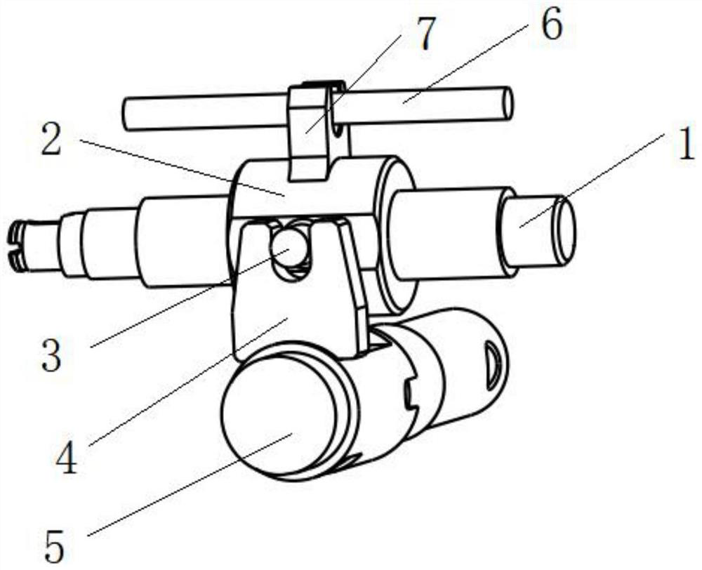
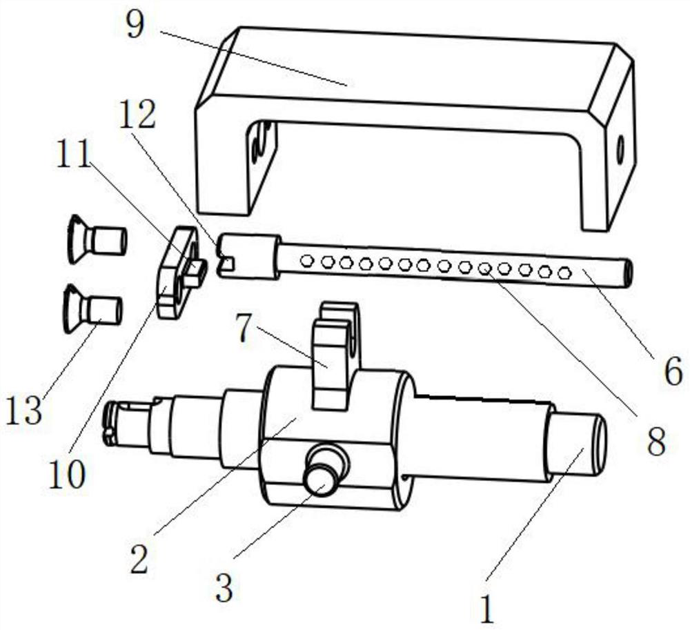
[0042] A specific embodiment of the present invention, such as Figure 1-9 As shown, a servo mechanism with a guide rail and a ball screw pair is disclosed, including: a lead screw 1, a ball nut 2, a guide rail 6, a shift fork 4 and an output shaft 5, wherein the lead screw 1 and the ball nut 2 form a screw Lever nut pair.

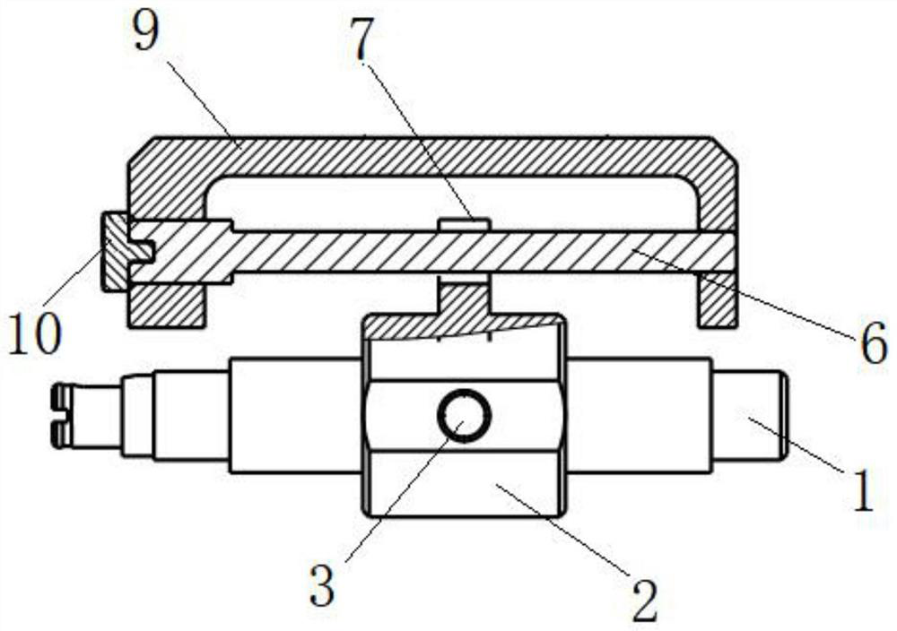
[0043] Further, as figure 1 As shown, the ball nut 2 is provided with a lug 7 and a trunnion 3, the lug 7 is provided with a U-shaped groove, and the lug 7 is matched with the guide rail 6 through the U-shaped groove and can slide relatively; when the lead screw 1 rotates, The ball nut 2 slides along the guide rail 6, and the shift fork 4 is undulated by the trunnion 3, and the output shaft 5 is driven by the shift fork 4 to rotate through a certain angle.

[0044] Further, as Figure 4 As shown, the lug 7 and the trunnion 3 are both integrally formed with the ball nut 2, and the lug 7 and the trunnion 3 are perpendicular to each other.

[0045] Furthe...

Embodiment 2

[0078] A specific embodiment of the present invention provides a transmission method of the servo mechanism in which the guide rail and the ball screw pair cooperate with the guide rail in the first embodiment, including the following steps:

[0079] Step S1: the motor drives the lead screw 1 to rotate;

[0080] Step S2: the lead screw 1 and the ball nut 2 form a lead screw nut pair, and the lead screw 1 drives the ball nut 2 to slide along the guide rail 6;

[0081] Step S3: The trunnion 3 slides the ball nut 2 synchronously, and drives the output shaft 5 to deflect.

[0082] In the step S2, the ball nut 2 is matched with the guide rail 6 through the support lug 7; Side contact; when the ball nut 2 slides relative to the guide rail 6, the ball 8 rolls relative to the lug 7.

[0083] Through the contact between the balls 8 and the lugs 7, the sliding friction is replaced by rolling friction, and the line contact is replaced by point contact. In the process of sliding the bal...


PUM


Abstract

The invention relates to a servo mechanism with a guide rail matched with a ball screw pair and a transmission method of the servo mechanism, belongs to the technical field of servo transmission systems, and solves the problems that in the prior art, a ball screw pair generates a transmission gap due to sliding friction, so that a servo mechanism system generates a dead zone, and deflection precision is affected and even the system shakes. The servo mechanism comprises a lead screw, a ball nut, a guide rail, a transmission mechanism and an output shaft. A support lug matched with the guide rail is arranged above the ball nut; the supporting lugs make contact with balls on the guide rails and are guided through the guide rails, and a lead screw and a ball nut form a lead screw nut pair. The ball nut can linearly move in the guide rail direction. A trunnion is arranged on the ball nut, and when the trunnion moves linearly, the output shaft can be driven to rotate through the transmission mechanism.

Description

technical field [0001] The invention relates to the technical field of servo transmission systems, in particular to a servo mechanism in which a guide rail and a ball screw pair are matched and a transmission method thereof. Background technique [0002] With the development of the steering gear towards the miniaturization of the structure, the requirements for the utilization of the internal space of the steering gear are constantly increasing. The transmission form of shift fork + ball screw pair is compact in structure and high in transmission efficiency, and has been widely used in fly-on servos and other servo system transmission mechanisms. In the transmission form of shift fork + ball screw pair (mainly composed of ball nut and ball screw), the ball nut trunnion slides in the U-shaped groove of the shift fork to convert the linear motion of the ball nut into output The rotary motion of the shaft has been widely used in small servo mechanisms due to its compact struct...

Claims


Application Information

Patent Timeline
Patent Type & Authority Applications(China)
IPC IPC(8): F16H25/22
CPCF16H25/2204
Inventor 杨得亮谢潼韩士玉马俊
Owner BEIJING MECHANICAL EQUIP INST
Why Eureka
Try Eureka