Method for optimizing resonant frequency detection

A technology of resonant frequency and resonant frequency point, which is applied in the field of optimizing resonant frequency detection to achieve the effect of reducing measurement error and offsetting delay error.

Pending Publication Date: 2022-07-29
SOUTHEAST UNIV
View PDF0 Cites 0 Cited by
  • Summary
  • Abstract
  • Description
  • Claims
  • Application Information

AI Technical Summary

Problems solved by technology

[0005] Aiming at the deficiencies in the method of frequency scanning detection of resonance frequency in the prior art, the present invention proposes a method of

Method used


Image

  • Method for optimizing resonant frequency detection
  • Method for optimizing resonant frequency detection

Examples


Embodiment Construction

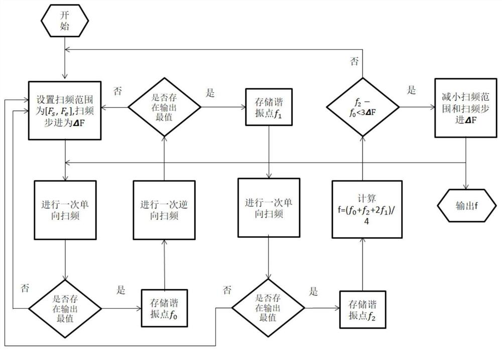
[0029] A method for optimizing resonance frequency detection of the present invention, such as figure 2 shown, including the following steps:

[0030] Step 1, set the sweep range [F s ,F e ] and sweep frequency step ΔF to perform a forward sweep;

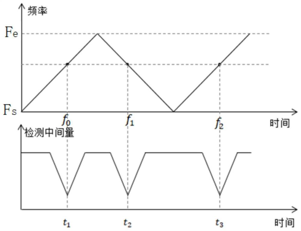
[0031] Step 2: According to the change of the output intermediate quantity during the frequency sweep, it is judged whether there is an extreme value of the output intermediate quantity in this frequency sweep. According to different detection scenarios, the intermediate quantity can be voltage or current, figure 1 shown; if there is no extreme value, increase the sweep range and sweep step and re-sweep, for example, F s =F s -ΔF es , F e =F e +ΔF es , return to step 1;

[0032] If there is an extreme value, output the sweep frequency when the intermediate amount reaches the extreme extreme as the resonant frequency point f 0 ;

[0033] Step 3, perform a reverse frequency sweep, the sweep frequency range is [F e , F ...


PUM


Abstract

The invention discloses a method for optimizing resonant frequency detection, and the method effectively reduces the measurement error caused by the fluctuation to be measured during the frequency sweeping period through the comparison of two adjacent same-direction frequency sweeping results. The sweep frequency range and the step are dynamically adjusted according to the detection result, so that the system can be effectively operated, and the contradiction among the detection time, the sweep frequency range and the sweep frequency step is solved; a direction alternating frequency sweeping scheme is adopted, the delay error of the system is counteracted, and the delay of the system is fixed in an ideal state, so that the offset of the resonant frequency is equal in two frequency sweeping directions.

Description

technical field [0001] The invention belongs to the field of sensor detection, in particular to a method for optimizing resonance frequency detection based on the principle of inductive inductive coupling. Background technique [0002] The principle of inductive coupling refers to the mutual induction or coupling of two inductances that are close to each other due to the electromagnetic induction effect. Since the two inductors do not need to be directly connected by wires to achieve signal transmission, wireless energy transmission and information transmission can be achieved, so the principle of inductive coupling has been widely used in wireless charging, sensors and other fields. [0003] In the field of sensors, the principle of inductive coupling has been applied to displacement detection, pressure detection, flow detection, temperature and humidity detection and many other detection fields. In these sensors, the resonant frequency of the LC resonant tank is often det...

Claims


Application Information

Patent Timeline
IPC IPC(8): G01R23/02
CPCG01R23/02
Inventor 吴俊王元威张驰唐俊逸刘道森向盛鑫
Owner SOUTHEAST UNIV
Why Eureka
Try Eureka