Broken line detection method and detection device for standby power supply of variable pitch of fan
A backup power supply and disconnection detection technology, which is applied in the direction of power supply testing, measuring devices, measuring electricity, etc., can solve problems such as narrow range, small charging current, and few detection times, so as to reduce the impact on life, stable and reliable detection, and easy engineering effect
- Summary
- Abstract
- Description
- Claims
- Application Information
AI Technical Summary
Problems solved by technology
Method used
Image
Examples
Embodiment 1
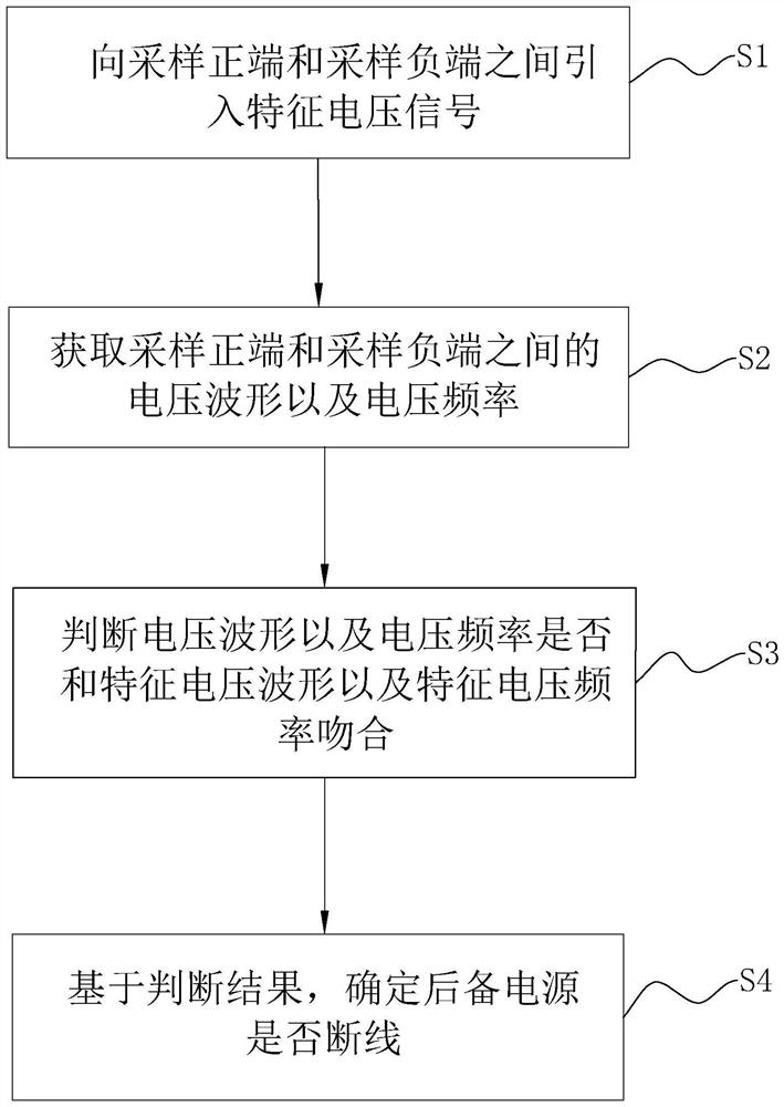
[0046] The embodiment of the present application discloses a method for detecting a disconnection of a fan pitch backup power supply. refer to figure 1 , The method for detecting the disconnection of the back-up power supply for variable pitch of the fan includes the following steps.
[0047] S1. Introduce a characteristic voltage signal between the sampling positive terminal and the sampling negative terminal.
[0048] The sampling positive terminal is the connection terminal between the positive pole of the backup power supply and the power supply positive pole of the rectified output of the three-phase power supply, and the sampling negative terminal is the connection terminal between the negative pole of the backup power supply and the power supply negative pole of the rectified output of the three-phase power supply. When the backup power supply is not connected, the characteristic voltage signal between the sampling positive terminal and the sampling negative terminal i...
Embodiment 2
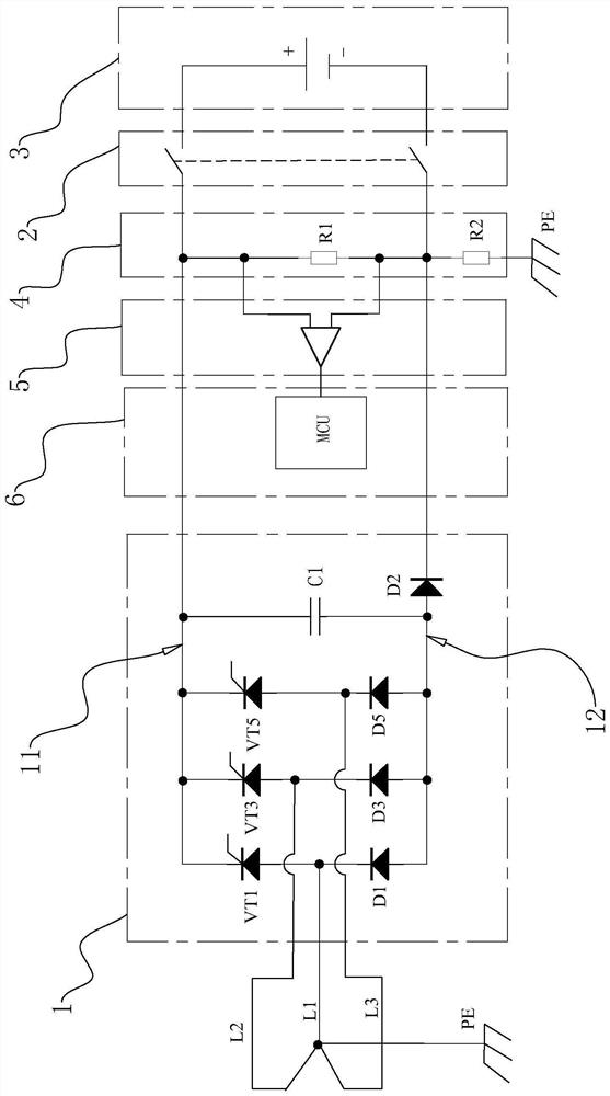
[0057] The embodiment of the present application discloses a disconnection detection device for a fan pitch backup power supply. refer to figure 2 , The fan pitch backup power disconnection detection device includes a three-phase rectifier module 1, a backup switch module 2, a backup power module 3, a resistance voltage divider module 4, a differential operation module 5 and a main control module 6. The resistance voltage divider module 4 and the backup switch module 2 are sequentially connected between the three-phase rectifier module 1 and the backup power supply module 3, the differential operation module 5 is connected to the resistance voltage divider module 4, and the main control module 6 is connected to the differential operation module 5. . The output of the three-phase rectifier module 1 includes a positive bus bar 11 and a negative bus bar 12. The resistance voltage divider module 4 is connected to the positive bus bar 11 and the negative bus bar 12, and is also c...
Embodiment 3
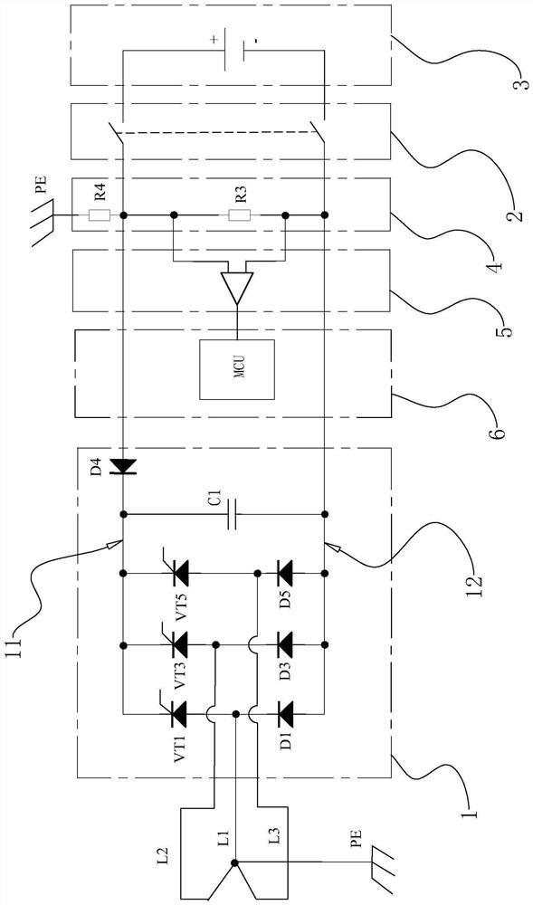
[0068] refer to image 3 , the difference between the embodiment of the present application and the embodiment 2 is that a second blocking diode D4 is connected in series on the positive bus bar 11 to limit the current on the positive bus bar 11, so that the voltage between the negative bus bar 12 and the characteristic terminal is used as the characteristic voltage signal . The cathode of the second blocking diode D4 is connected to the output terminal of the three-phase rectifier module 1 where the positive bus 11 is located, and the anode of the second blocking diode D4 is connected to the sampling negative terminal.
[0069] And at this time, the resistor divider module 4 includes a third resistor R3 and a fourth resistor R4, the third resistor R3 is connected in series between the sampling positive terminal and the sampling negative terminal, and the fourth resistor R4 is connected in series between the sampling positive terminal and the characteristic terminal. . In th...
PUM
 Abstract
Description
Claims
Application Information
 - R&D
- Intellectual Property
- Life Sciences
- Materials
- Tech Scout
- Unparalleled Data Quality
- Higher Quality Content
- 60% Fewer Hallucinations
Browse by: Latest US Patents, China's latest patents, Technical Efficacy Thesaurus, Application Domain, Technology Topic, Popular Technical Reports.
© 2025 PatSnap. All rights reserved.Legal|Privacy policy|Modern Slavery Act Transparency Statement|Sitemap|About US| Contact US: help@patsnap.com


