Control device capable of being remotely operated for maintenance of transformer substation

A remote operation and control device technology, applied in substation/switch layout details, substations, closed substations, etc., can solve the problems of reducing the overall applicable life, inconvenient use, and unable to guarantee the overall safety of the device, so as to improve the applicable life, The effect of easy operation

Pending Publication Date: 2022-07-29
STATE GRID CORP OF CHINA +1
View PDF0 Cites 0 Cited by
  • Summary
  • Abstract
  • Description
  • Claims
  • Application Information

AI Technical Summary

Problems solved by technology

[0003] The existing device cannot guarantee the overall safety of the device, and cannot avoid damage to the main body of the controller due to unexpected impact, which reduces the overall service life, is inconvenient to use, cannot adjust the height, cannot adapt to the height of practical personnel, and is inconvenient to operate, which canno

Method used


Image

  • Control device capable of being remotely operated for maintenance of transformer substation
  • Control device capable of being remotely operated for maintenance of transformer substation
  • Control device capable of being remotely operated for maintenance of transformer substation

Examples


Example Embodiment

[0031] Example 1

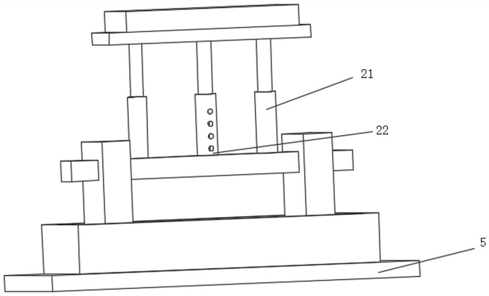
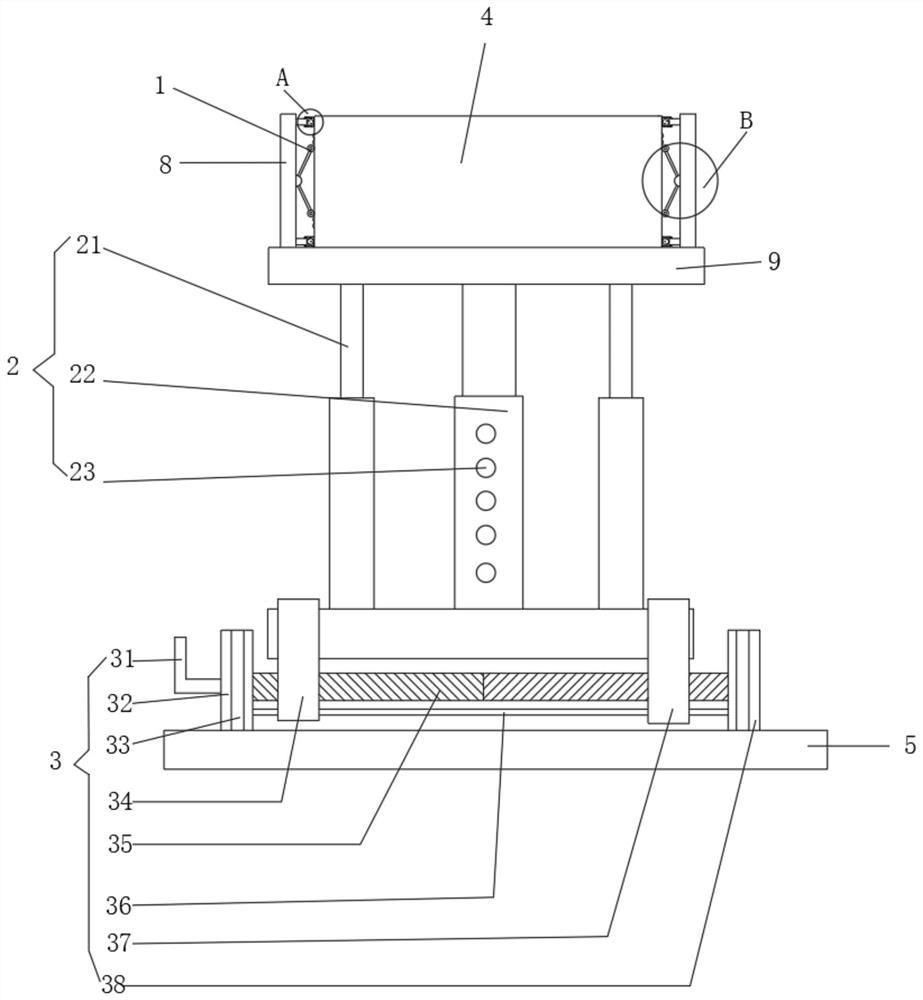
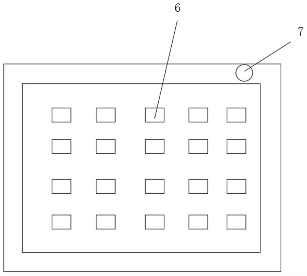
[0032] see Figure 1-6, a remotely operable control device for substation maintenance, comprising a base 5, a mounting mechanism 3 is fixedly installed on the top of the base 5, a lifting mechanism 2 is fixedly mounted on the base 5 through the mounting mechanism 3, and a top block 9 is fixedly mounted on the top of the lifting mechanism 2 , a protective mechanism 1 is fixedly installed on both sides of the top of the top block 9, a controller main body 4 is installed in the middle of the top of the top block 9, a side plate 8 is fixedly installed on the outer side of the protective mechanism 1, and a button 6 is arranged on the top of the controller main body 4. The top of the outer wall of the main body 4 is provided with a signal transmitter 7;

[0033] The protection mechanism 1 includes a connecting rod 16, the connecting rod 16 is hinged to the inner side of the side plate 8, a buffer wheel 15 is installed in a section of the connecting rod 16 to rota...

Example Embodiment

[0035] Embodiment 2

[0036] see Figure 1-6 , and on the basis of the first embodiment, it is further obtained that the lifting mechanism 2 includes an adjusting rod 22, the adjusting rod 22 is fixedly installed on the top of the middle of the base 5, and the front of the adjusting rod 22 is provided with a card slot 23, and the adjusting rod 22 is clamped through the card slot 23. There is a buckle 24, a bar 26 is fixedly installed on the back of the buckle 24, a spring 27 is fixedly installed on the back of the bar 26, a box 25 is sleeved on the outer surface of the spring 27, and electric telescopic rods are fixedly installed on both sides of the adjustment rod 22 through the base 5 twenty one.

[0037] Further, a top block 9 is fixedly installed on the top of the electric telescopic rod 21, and a top block 9 is fixedly installed on the top of the adjusting rod 22. The box 25 is provided with a slot corresponding to the position of the buckle 24, and the box 25 is slidabl...

Example Embodiment

[0038] Embodiment 3

[0039] see Figure 1-6 , and on the basis of Embodiment 1 and Embodiment 2, it is further obtained that the installation mechanism 3 includes a first installation plate 32, the first installation plate 32 is fixedly installed on the left side of the top of the base 5, and a handle is fixedly installed on the left side of the first installation plate 32 31. A two-way threaded rod 35 is fixedly installed on the right side of the first mounting plate 32, a first threaded sleeve 34 is installed on the left outer thread of the two-way threaded rod 35, and a sliding rod 36 is slidably installed inside the first threaded sleeve 34. The first installation plate A panel 33 is fixedly mounted on the front of 32 , a second threaded sleeve 37 is threadedly mounted on the right outer surface of the bidirectional threaded rod 35 , and a second mounting plate 38 is fixedly mounted on the other side of the bidirectional threaded rod 35 away from the first mounting plate ...


PUM


Abstract

The invention relates to the technical field of remote control, and discloses a remotely operable control device for substation maintenance, which comprises a base, a mounting mechanism is fixedly mounted at the top of the base, a lifting mechanism is fixedly mounted on the base through the mounting mechanism, and a top block is fixedly mounted at the top of the lifting mechanism. Protection mechanisms are fixedly installed on the two sides of the top of the top block, a controller body is arranged in the middle of the top of the top block, and side plates are fixedly installed on the outer sides of the protection mechanisms. The control device comprises a protection mechanism, when the device is impacted by external force, the impact force enables the angle of a connecting rod to be increased, the connecting rod pushes a buffer wheel, the buffer wheel rotates at the position of a protruding block, the impact force is reduced, meanwhile, the buffer rod stretches out and draws back, pressure extrudes the position of an air bag, and the impact force is further buffered; the overall safety of the device is ensured, the internal damage of the controller main body caused by accidental impact force is avoided, and the overall service life is prolonged.

Description

technical field [0001] The invention relates to the technical field of remote control, in particular to a remotely operable control device for substation maintenance. Background technique [0002] A substation is a place in the power system that converts voltage and current, receives and distributes electrical energy. The substation in the power plant is a step-up substation. Its function is to boost the electric energy generated by the generator and feed it to the high-voltage power grid. The substation is to assemble some equipment to cut off or connect, change or adjust the voltage. In the power system, the substation is the gathering point of power transmission and distribution. The substation is mainly divided into: step-up substation, main network substation, secondary substation, distribution station, remote operation technology can be applied to network automation management, real-time monitoring and computer In terms of teaching, etc., the remote operation software...

Claims


Application Information

Patent Timeline
IPC IPC(8): H02B1/54H02B1/50H02B7/00
CPCH02B1/54H02B1/505H02B7/00
Inventor 洪启刚李方杰鲁勇山张力文赵峰
Owner STATE GRID CORP OF CHINA
Why Eureka
Try Eureka