Flame-proof structure at cable joint of telecommunication equipment

A kind of cable joint, equipment technology

Inactive Publication Date: 2022-07-29
天津超越科技有限公司
View PDF0 Cites 0 Cited by
  • Summary
  • Abstract
  • Description
  • Claims
  • Application Information

AI Technical Summary

Problems solved by technology

By analyzing the cause of the burning at the cable joint, it is found that the main reason is that the joint is prone to local overheating, and after the joint is continuously oxidized, the connection is likely to cause a short circuit and cause spontaneous combustion.

Method used


Image

  • Flame-proof structure at cable joint of telecommunication equipment
  • Flame-proof structure at cable joint of telecommunication equipment
  • Flame-proof structure at cable joint of telecommunication equipment

Examples


Embodiment Construction

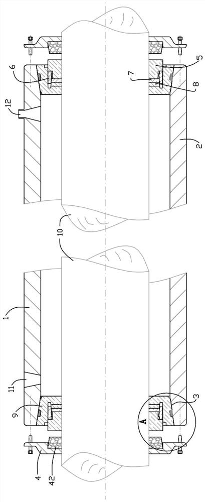
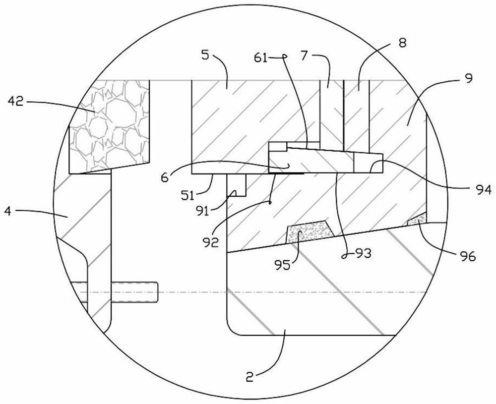
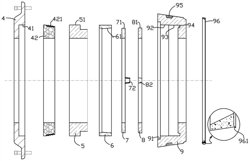
[0035] like Figure 1 to Figure 4 The flame-proof structure at the cable joint of telecommunication equipment as shown includes an upper half-pipe body 1 and a lower half-pipe body 2 that can be fastened to form a pipe body, and a cover plate 4 that is respectively arranged at both ends of the buckled pipe body. , a pressure ring 5 , a plug ring 6 , the first elastic ring 7 and the second elastic ring 8 used in pairs, and two sets of component units of the cone ring 9 .

[0036] Conical countersunk holes 3 are respectively formed at both ends of the pipe body formed by the upper half-pipe body 1 and the lower half-pipe body 2, and the two sets of component units are correspondingly matched to the two conical holes. Counterbore 3.

[0037] The cable 10 is matched with the shaft holes formed on the cover plate 4 , the pressure ring 5 , the plug ring 6 , the first elastic ring 7 , the second elastic ring 8 and the cone ring 9 respectively . That is, the cable 10 passes through...


PUM


Abstract

A flame-proof structure at a cable joint of telecommunication equipment comprises an upper half pipe body, a lower half pipe body and two groups of assembly units, wherein each assembly unit comprises a cover plate, a pressing ring, a plug ring, at least one pair of elastic rings and a conical surface ring. And a glue injection hole and an exhaust pipe joint are arranged on the upper half pipe body. And the conical surface ring is arranged in a conical counter bore formed in the end part of the pipe body formed by buckling the upper half pipe body and the lower half pipe body. An outer counter bore, a threaded hole section and an unthreaded hole section are sequentially formed in the conical surface ring in the axial direction, and an annular groove is formed in the bottom face of the unthreaded hole section. A taper hole is formed in the plug ring, and the side face of the elastic ring is a conical face and can be matched with the taper hole of the plug ring. The plug ring is matched with the unthreaded hole section, and the pressing ring is matched with the threaded hole section and can push the plug ring to move towards the inner end of the unthreaded hole section so that the inner end of the plug ring can be inserted into the annular groove. The cover plate is fixed at the end parts of the upper and lower half pipe bodies; and the inner end surface of the cover plate presses the outer end surface of the pressing ring. According to the utility model, the joint position can be effectively prevented from being oxidized too fast, and the joint position of the cable can still keep good flame-proof capability after being used for a long time.

Description

technical field [0001] The invention relates to the technical field of telecommunication equipment cable connection, in particular to a flame-proof structure used at the joint of telecommunication equipment cable connection. Background technique [0002] In the field of telecommunications equipment, cables are used to transmit power to the equipment. Relying on past operating experience, the faults of cables used in the telecommunications field are mostly concentrated at the joints between cables and cables, and the main problem is combustion. By analyzing the reasons for the burning of the cable joints, it is found that the main reason is that the joints are prone to local overheating, and after the joints are continuously oxidized, the connection positions are likely to cause short circuits and cause spontaneous combustion. SUMMARY OF THE INVENTION [0003] The purpose of the present invention is to provide a flame-proof structure at the cable joint of telecommunication...

Claims


Application Information

Patent Timeline
Patent Type & Authority Applications(China)
IPC IPC(8): H02G15/18
CPCH02G15/18
Inventor 王丕霞
Owner 天津超越科技有限公司
Why Eureka
Try Eureka