Wind power main shaft coating equipment

A wind power spindle and coating equipment technology, applied in wind power generation, spraying devices and other directions, can solve the problems of not being able to spray the side wall of the wind power spindle at the same time, reducing the coating efficiency of the wind power spindle, etc., to improve the use flexibility and improve the coating. Efficiency, the effect of meeting the needs of the work

Pending Publication Date: 2022-08-02
SHANDONG LAIWU JINLEI WIND POWER TECH
View PDF2 Cites 0 Cited by
  • Summary
  • Abstract
  • Description
  • Claims
  • Application Information

AI Technical Summary

Problems solved by technology

[0005] In the existing coating equipment, usually only the channel wall of the wind power main shaft can be sprayed, but the side wall of the wind power main shaft cannot be sprayed at the same time, so that the coating efficiency of the wind power main shaft is reduced
For example, the Chinese patent with the application number CN201921174919.7 discloses "A Device for Spraying the Inner Hole Wall of th

Method used


Image

  • Wind power main shaft coating equipment
  • Wind power main shaft coating equipment
  • Wind power main shaft coating equipment

Examples


Embodiment 1

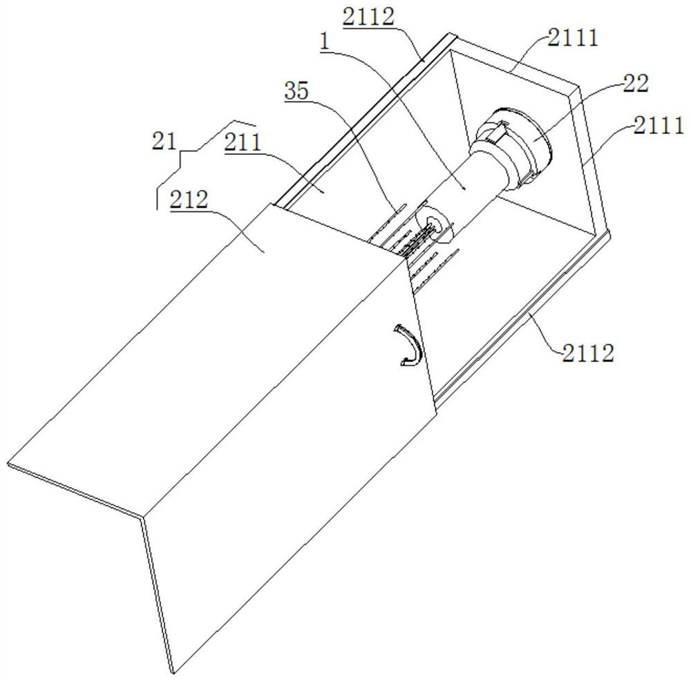
[0058] like Figure 1-5 As shown, a wind power main shaft coating equipment includes a supporting mechanism and a spraying mechanism.

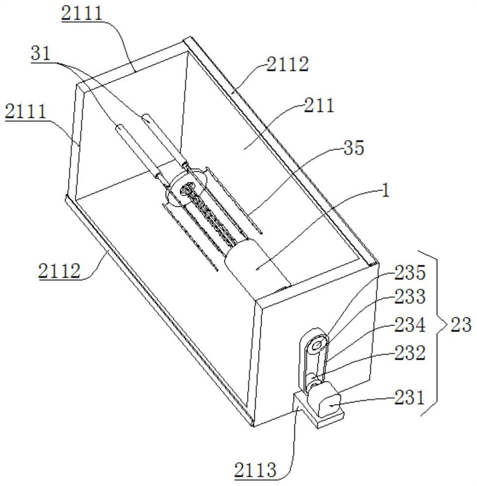
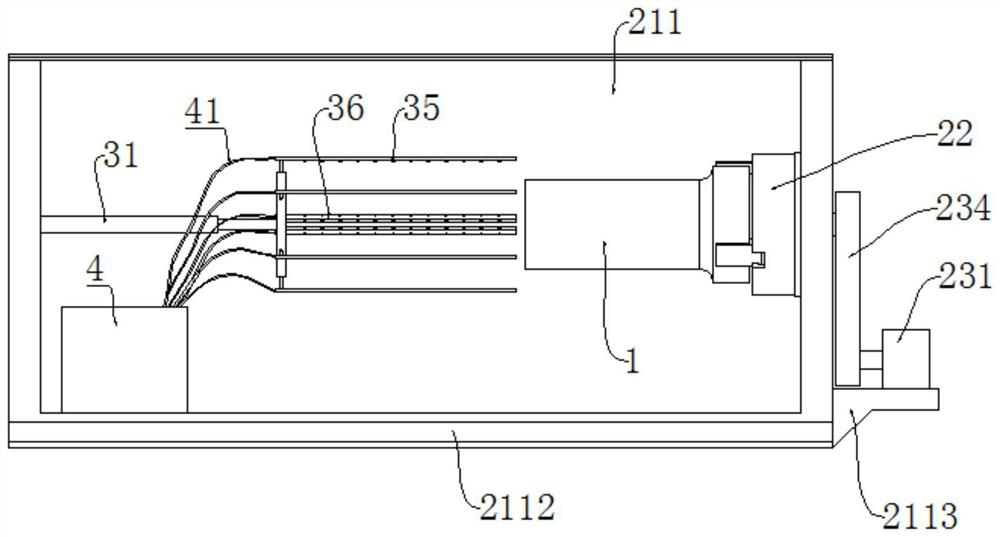
[0059] The support mechanism is used to support the wind power main shaft 1 to be painted. The support mechanism includes a protective box 21 , a clamp 22 and a driving member 23 .

[0060] The protective case 21 includes a case body 211 and a transparent cover 212 . The box top of the box body 211 and the front box wall of the box body 211 are provided with openings 2111 . The box body 211 is provided with a transparent cover 212 for blocking the opening 2111 , and the transparent cover 212 can be a transparent plastic cover. Specifically, sliding rails 2112 are fixedly installed on the top of the box body 211 and the front box wall of the box body 211 , the long sides of the sliding rails 2112 are arranged along the left and right directions of the box body 211 , and the transparent cover 212 is provided with a sliding groove ( (not shown...

Embodiment 2

[0070] The present embodiment 2 makes the following improvements on the basis of the embodiment 1: such as Figure 6-14 As shown, in a wind power main shaft coating equipment of the second embodiment, the spraying mechanism further includes a driving ring 39 and a fixing member 310 .

[0071] The support ring 32 is provided with a accommodating cavity inside, the outer ring wall of the support ring 32 is provided with an outer sliding hole, the inner ring wall of the supporting ring 32 is provided with an inner sliding hole, and both the inner sliding hole and the outer sliding hole are communicated with the accommodating cavity , the end surface of the support ring 32 is provided with a guide hole 3214, and the guide hole 3214 is also communicated with the accommodating cavity.

[0072] The support ring 32 includes two ring bodies 321 arranged side by side, and the two ring bodies 321 are provided with an accommodating groove 3211 , an outer sliding groove 3212 and an inner s...


PUM


Abstract

The wind power main shaft coating equipment comprises a supporting mechanism and a spraying mechanism, the supporting mechanism comprises a protection box, a clamp and a driving part, the clamp used for clamping the front end of a wind power main shaft is arranged on the inner wall of the protection box, and the driving part used for driving the clamp to rotate is arranged on the outer side wall of the protection box; the spraying mechanism comprises a telescopic rod, a supporting ring, outer supporting rods, inner supporting rods, outer spraying pipes and inner spraying pipes, the telescopic rod used for pushing the supporting ring to the direction where the clamp is located is arranged on the inner wall of the protection box, the outer supporting rods are arranged on the outer ring wall of the supporting ring, and the inner supporting rods are arranged on the inner ring wall of the supporting ring. An outer spraying pipe used for spraying the outer side wall of the wind power main shaft is arranged on the outer supporting rod, and an inner spraying pipe used for spraying the channel wall of the wind power main shaft is arranged on the inner supporting rod. The coating efficiency of the wind power main shaft can be improved.

Description

technical field [0001] The invention relates to the technical field of processing equipment for wind power spindles, in particular to a wind power spindle coating equipment. Background technique [0002] The wind power spindle is the part used to transmit torque in the wind turbine. The front end of the wind power spindle is provided with a hub connection flange. The hub connection flange is used to connect with the hub. The hub is the base of the fixed blade. The blades are installed on the hub to form a wind turbine. The rear end of the wind power main shaft is connected to the gearbox, and the shaft center of the wind power main shaft is provided with a through hole, and the through hole is the channel for the control cable, oil circuit or mechanical rod of the pitch mechanism. [0003] Since the side wall of the wind power spindle needs to cooperate with the bearings in the wind turbine, the side wall of the wind power spindle is prone to rust and wear. Once the side wal...

Claims


Application Information

Patent Timeline
IPC IPC(8): B05B13/02B05B13/06
CPCB05B13/0207B05B13/0278B05B13/0627Y02E10/72
Inventor 伊廷雷孙伟孙双李新生张振蔺立元刘哲程林刘永超杨开彬
Owner SHANDONG LAIWU JINLEI WIND POWER TECH
Why Eureka
Try Eureka