Powder storage device for machine tool machining
A storage device and powder technology, which is applied in the direction of metal processing equipment, metal processing machinery parts, manufacturing tools, etc., can solve the problems of poor powder storage effect, and achieve the effect of improving the effect, convenient storage and processing, and low production cost
- Summary
- Abstract
- Description
- Claims
- Application Information
AI Technical Summary
Problems solved by technology
Method used
Image
Examples
Embodiment 1
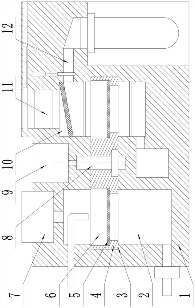
[0022] like figure 1 As shown, this specific embodiment adopts the following technical solutions: a powder storage device processed by a machine tool, comprising a shell 1, an inner cavity 2, a connecting cavity 3, a turntable 4, a filter plate 5, a filter groove 6, and a powder suction mechanism 7 , drive shaft 8, motor 9, inner cavity 2 10, drying structure 11 and storage mechanism 12; inner cavity 1 2 is provided inside the left side of the housing 1, and inner cavity 2 10 is arranged inside the right side of the housing 1 , a connecting cavity 3 is provided in the center of the left side of the housing 1; A turntable 4 is movably connected inside the connection cavity 3, and a transmission shaft 8 is fixedly connected inside the center of the turntable 4; a plurality of filter slots 6 are arranged around the turntable 4, and a filter plate 5 is fixedly connected to the lower side of the filter slot 6; The powder suction mechanism 7 is arranged inside the inner cavity 1 2;...
Embodiment 2
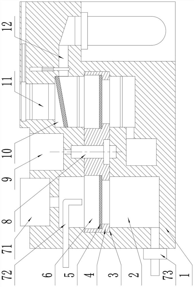
[0024] like figure 1 As shown, this specific embodiment adopts the following technical solutions: a powder storage device processed by a machine tool, comprising a shell 1, an inner cavity 2, a connecting cavity 3, a turntable 4, a filter plate 5, a filter groove 6, and a powder suction mechanism 7 , drive shaft 8, motor 9, inner cavity 2 10, drying structure 11 and storage mechanism 12; inner cavity 1 2 is provided inside the left side of the housing 1, and inner cavity 2 10 is arranged inside the right side of the housing 1 , a connecting cavity 3 is provided in the center of the left side of the housing 1; A turntable 4 is movably connected inside the connection cavity 3, and a transmission shaft 8 is fixedly connected inside the center of the turntable 4; a plurality of filter slots 6 are arranged around the turntable 4, and a filter plate 5 is fixedly connected to the lower side of the filter slot 6; The powder suction mechanism 7 is arranged inside the inner cavity 1 2;...
Embodiment 3
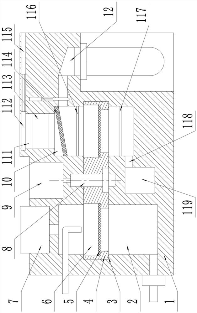
[0029] like figure 1 As shown, this specific embodiment adopts the following technical solutions: a powder storage device processed by a machine tool, comprising a shell 1, an inner cavity 2, a connecting cavity 3, a turntable 4, a filter plate 5, a filter groove 6, and a powder suction mechanism 7 , drive shaft 8, motor 9, inner cavity 2 10, drying structure 11 and storage mechanism 12; inner cavity 1 2 is provided inside the left side of the housing 1, and inner cavity 2 10 is arranged inside the right side of the housing 1 , a connecting cavity 3 is provided in the center of the left side of the housing 1; A turntable 4 is movably connected inside the connection cavity 3, and a transmission shaft 8 is fixedly connected inside the center of the turntable 4; a plurality of filter slots 6 are arranged around the turntable 4, and a filter plate 5 is fixedly connected to the lower side of the filter slot 6; The powder suction mechanism 7 is arranged inside the inner cavity 1 2;...
PUM
 Abstract
Description
Claims
Application Information
 - R&D
- Intellectual Property
- Life Sciences
- Materials
- Tech Scout
- Unparalleled Data Quality
- Higher Quality Content
- 60% Fewer Hallucinations
Browse by: Latest US Patents, China's latest patents, Technical Efficacy Thesaurus, Application Domain, Technology Topic, Popular Technical Reports.
© 2025 PatSnap. All rights reserved.Legal|Privacy policy|Modern Slavery Act Transparency Statement|Sitemap|About US| Contact US: help@patsnap.com


