Pitched roof structure of prefabricated floor slab, construction method and prefabricated floor slab

A technology for sloping roofs and floor slabs, which is applied to roofs, roofs, and roof coverings using flat/curved panels, can solve problems such as difficulty in pouring compactness control, concrete slippage or segregation, and high labor intensity for workers, so as to reduce moisture content. Work workload and formwork workload, reduce construction difficulty and labor intensity of workers, and simplify the effect of construction difficulty

Pending Publication Date: 2022-08-02
GUANGDONG PROVINCE COMM PLANNING & DESIGN INST
View PDF11 Cites 0 Cited by
  • Summary
  • Abstract
  • Description
  • Claims
  • Application Information

AI Technical Summary

Problems solved by technology

[0004] ⑴This construction method is only suitable for sloping roofs with low slopes
[0005] (2) It is easy to cause concrete slipping or segregation during the construction process, and there are problems such as difficulty in pouring compactness control and poor construction quality
[0006] (3) The pouring process is quite cumbersome, and there are problems such as time-consuming and labor-intensive workers

Method used


Image

  • Pitched roof structure of prefabricated floor slab, construction method and prefabricated floor slab
  • Pitched roof structure of prefabricated floor slab, construction method and prefabricated floor slab
  • Pitched roof structure of prefabricated floor slab, construction method and prefabricated floor slab

Examples


Embodiment 1

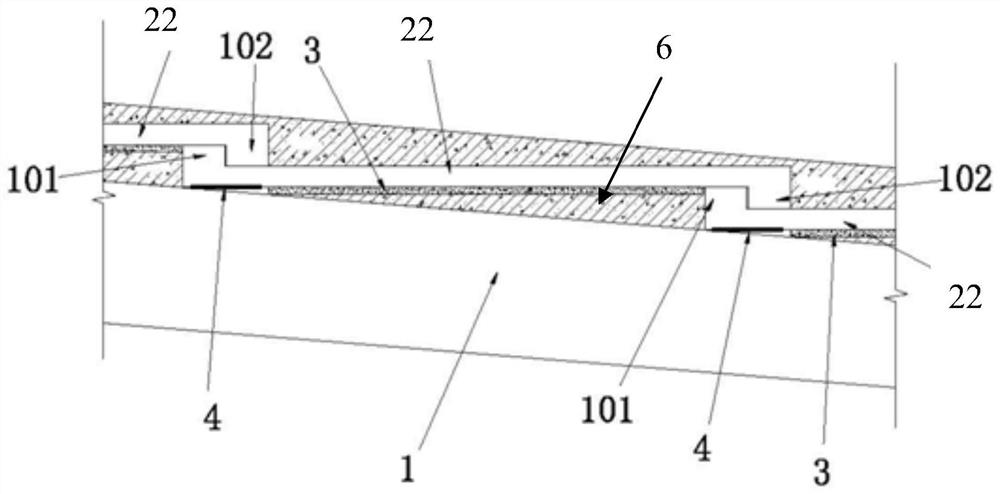
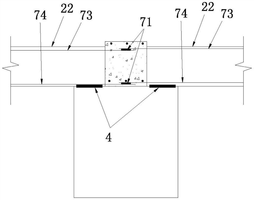
[0043] like figure 1 and figure 2 As shown, it is a prefabricated floor sloping roof structure of the present invention, which includes a frame beam 1 and several prefabricated floor slabs 22 laid on the frame beam 1. It should be noted that the cross section of the frame beam 1 is generally rectangular or T-shaped. , In the assembled monolithic frame structure, the frame beam 1 is often made into a rectangular section, the prefabricated floor slabs 22 are continuously arranged in rows along the slope direction of the sloping roof, and several rows of prefabricated floor slabs 22 are arranged at intervals along the direction perpendicular to the slope. It can be understood that Therefore, a plurality of prefabricated floor slabs 22 are laid on a plurality of frame beams 1 arranged at intervals in a matrix manner, two adjacent prefabricated floor slabs 22 in each column are connected by a snap structure, and the prefabricated floor slabs 22 in each horizontal row are arranged ...

Embodiment 2

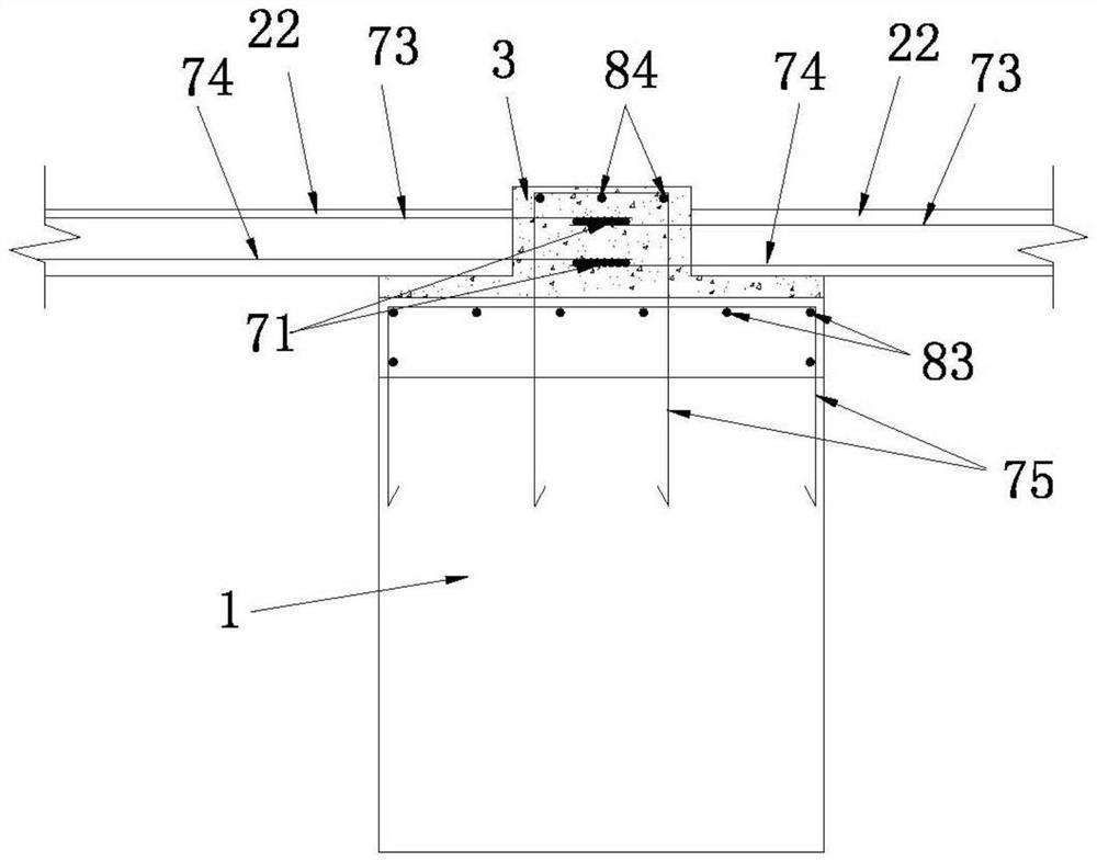
[0055] like image 3 As shown, the difference between the prefabricated floor slab sloping roof structure of this embodiment and Embodiment 1 is that the prefabricated floor slab 22 and the frame beam 1 are fixed in different ways, no neoprene pad is provided, and the top surface of the frame beam 1 is anchored into the insert reinforcement. 75. The anchored bar 75 is a closed stirrup. The closed stirrup is formed by cross-connecting two U-shaped stirrups. One of the U-shaped stirrups is embedded in the top of the frame beam 1, with a diameter of 12mm and a spacing of 200mm. The stirrups are bent, and the inner side is bound with a plurality of first longitudinal bars 83 with HRB600 diameter of 12mm arranged at intervals; the lower part of another U-shaped stirrup is located in the frame beam 1, and the upper part extends out of the frame beam 1 to enter The concrete part is also formed by bending stirrups with a diameter of 12mm and a spacing of 200mm, and a plurality of seco...

Embodiment 3

[0059] like Figure 4 As shown, the difference between the prefabricated floor slab sloping roof structure of this embodiment and Embodiment 2 is that the frame beam 1 of this embodiment is a single-sided frame beam, and the beam gluten 73 and the beam bottom rib 74 of the prefabricated floor slab 22 are respectively welded by welding The connecting bars 71 connect the supporting bars 76 arranged in the length direction. The length of the supporting bars 76 is preferably 400 mm, and the supporting bars 76 are located in the closed portion of the insert bars.

[0060] Anchoring bars are placed on the top surface of the frame beam 1. The anchor bars are closed stirrups. The closed stirrups are formed by cross-connecting two U-shaped stirrups. One of the U-shaped stirrups is embedded in the frame beam 1. The inner top is formed by bending stirrups with a diameter of 12mm and a spacing of 200mm, and the inner side is bound with a plurality of third longitudinal bars 85 with a diam...


PUM


Abstract

The invention discloses a prefabricated floor pitched roof structure, a construction method and prefabricated floors, the prefabricated floor pitched roof structure comprises a frame beam and a plurality of prefabricated floors laid on the frame beam, the prefabricated floors are continuously arranged in rows in the gradient direction of a pitched roof, and the multiple rows of prefabricated floors are arranged at intervals in the direction perpendicular to the gradient. Every two adjacent prefabricated floor slabs in each row are connected through a buckle structure, gaps are formed between the prefabricated floor slabs and the frame beams, gaps communicated with the gaps are formed in the two sides of each row of prefabricated floor slabs, the gaps and the gaps are filled with concrete, all the prefabricated floor slabs and the frame beams are fixedly connected through the concrete, and every two adjacent prefabricated floor slabs are fixedly connected through the concrete. The prefabricated floor is simple and compact in structure, meets the safety requirement, is simple and convenient to assemble on site, reduces the construction difficulty and the labor intensity of workers, improves the working efficiency, has good drainage performance and rain leakage prevention, can select prefabricated floors of different specifications according to actual construction requirements, can be suitable for pitched roof structures with the gradient larger than 9 degrees, and is high in applicability.

Description

technical field [0001] The invention relates to a prefabricated floor sloping roof structure, a construction method for the prefabricated floor sloping roof structure, and a prefabricated floor used for the prefabricated floor sloping roof structure. Background technique [0002] With the development of the construction industry, people's life needs are diversified. In recent years, many novel and unique sloping roof structures have appeared in architectural design. [0003] The construction method of the traditional sloping roof structure is to first lay the slope bottom formwork on the frame beam or set a layer of steel mesh on the frame beam, and then form it by pouring and shooting. Therefore, this construction method has the following defects: [0004] (1) This construction method is only suitable for sloping roofs with lower slopes. [0005] (2) It is easy to cause concrete slippage or segregation during the construction process, and there are problems such as difficu...

Claims


Application Information

Patent Timeline
Patent Type & Authority Applications(China)
IPC IPC(8): E04B7/02E04D3/04E04D3/36E04D13/16E04D15/04
CPCE04B7/026E04D3/04E04D3/3605E04D13/1687E04D15/04Y02A30/60
Inventor 曾海峰李广海熊珺刘桂红何沛霖黄敏邓昭亮黄润江冯琮亮梁耀兵陈浩标梁健秋李柏祥陈宇权何传琪肖俊强熊翩杨倩雯杨洋曾为麟陈嵘泽林泳珊麦培民
Owner GUANGDONG PROVINCE COMM PLANNING & DESIGN INST
Why Eureka
Try Eureka