
Torque control method and device for mechanical throttle body, medium and vehicle

A technology of torque control and throttle body, applied in the direction of engine control, electrical automatic control, automatic control, etc., can solve the problems of poor drivability, power shock of the transmission system, etc., and achieve the effect of improving comfort.

Pending Publication Date: 2022-08-02
UNITED AUTOMOTIVE ELECTRONICS SYST
View PDF0 Cites 0 Cited by
  • Summary
  • Abstract
  • Description
  • Claims
  • Application Information

AI Technical Summary

Problems solved by technology

In this way, when the output torque is turned from negative to positive, the gear joint surface of the transmission system is switched from one side to the other, which will cause a dynamic impact on the transmission system; and in the process of periodic oil cut-off and oil supply, it will cause periodic Sexual power shock, power shock leads to poor drivability
[0004] The second is the "fuel supply" mode of torque response. When switching from the active state to the exit state, there is an obvious step in the output torque of the engine (for example: before entering the "exit" state, the realization method of the "fuel supply" mode is to cut off the oil 1 time - restore fuel supply once, at this time the engine output torque can be equivalent to 50% of the same working condition; after entering the "exit" state, the engine output torque can be equivalent to 100% of the same working condition, that is produces a torque step equivalent to 50% of the current operating condition), this output torque step may cause the EMS to enter the "torque response" state again (because the EMS output torque rises again), this "torque response state "-Frequent switching between "non-torque responsive states" can also lead to poor drivability

Method used


Image

  • Torque control method and device for mechanical throttle body, medium and vehicle
  • Torque control method and device for mechanical throttle body, medium and vehicle
  • Torque control method and device for mechanical throttle body, medium and vehicle

Examples


Embodiment Construction

[0063] To make the objects, advantages and features of the present invention clearer, the torque control method, device, medium and vehicle for a mechanical throttle body proposed by the present invention will be further described in detail below with reference to the accompanying drawings. It should be noted that, the accompanying drawings are all in a very simplified form and in inaccurate scales, and are only used to facilitate and clearly assist the purpose of explaining the embodiments of the present invention. It is to be understood that the drawings in the specification do not necessarily show specific structures of the invention to scale and that the illustrative features in the drawings for illustrating certain principles of the invention may also be shown in somewhat simplified form. The specific design features of the invention disclosed herein, including, for example, the specific dimensions, orientations, locations, and profiles will be determined in part by the sp...


PUM


Abstract

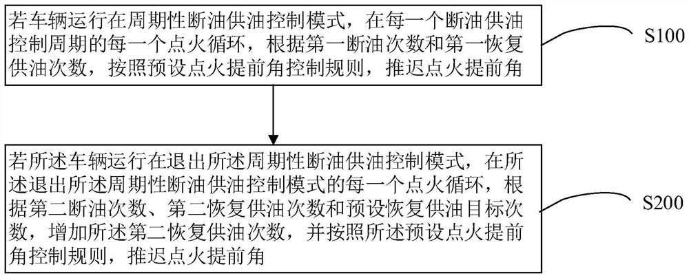
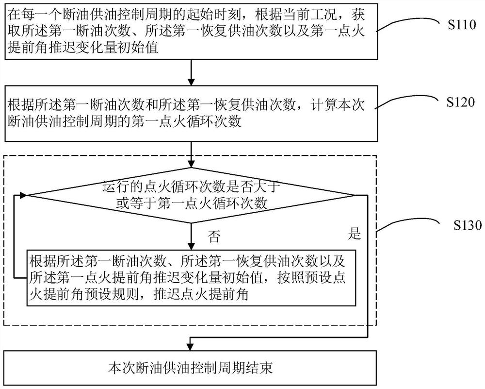
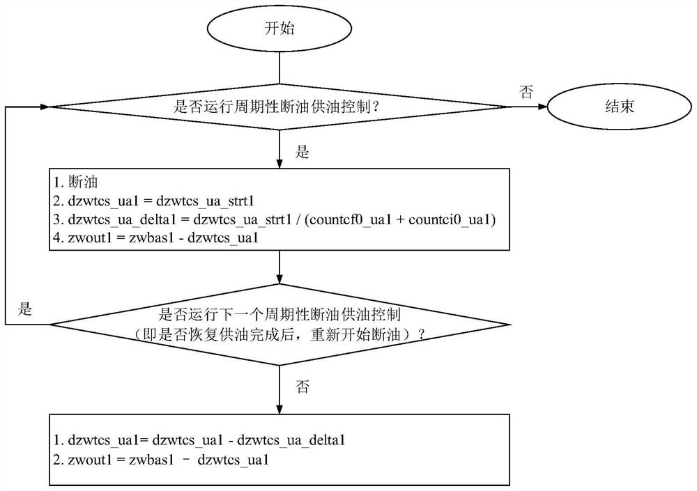
The invention provides a torque control method and device for a mechanical throttle body, a medium and a vehicle. When torque response is achieved, when the vehicle runs in a periodic fuel cut-off and fuel supply control mode, in each ignition cycle of each fuel cut-off and fuel supply control period, the ignition advance angle is delayed according to the first fuel cut-off frequency, the first fuel supply recovery frequency and the preset ignition advance angle control rule. When the vehicle runs in each ignition cycle of quitting the periodic fuel cut-off and fuel supply control mode and quitting the periodic fuel cut-off and fuel supply control mode, the second fuel supply recovery times are increased according to the second fuel cut-off times, the second fuel supply recovery times and the preset fuel supply recovery target times, and the ignition advance angle of the vehicle is controlled according to the preset ignition advance angle control rule. And the ignition advance angle is delayed. When the torque reduction requirement is responded, power impact of a transmission system can be reduced, smooth transition of torque is achieved in the process of quitting the torque response mode, and therefore the driving comfort is improved.

Description

technical field [0001] The present invention relates to the technical field of vehicle control, and in particular, to a torque control method, device, medium and vehicle for a mechanical throttle body. Background technique [0002] With the popularization of motorcycle EFI system and the advancement of electronic control technology, more and more personalized customized torque control functions are applied to motorcycle electronic control system (EMS), such as driving anti-skid function and upshift control function. Wait. The EMS regulates the output torque of the engine, which is transmitted to the road through the clutch-gearbox-reduction mechanism-drive wheel, and drives the motorcycle through the frictional force (effective driving force) between the road surface and the tires of the drive wheel. For mechanical throttle body (MGAS) motorcycles, the throttle opening is directly controlled by the driver, and the intake air volume is uncontrollable, resulting in two situat...

Claims


Application Information

Patent Timeline
IPC IPC(8): F02P5/145F02D9/08
CPCF02P5/145F02D9/08Y02T10/40
Inventor 郭石磊何文潇姜学敏瞿尧江兴宏
Owner UNITED AUTOMOTIVE ELECTRONICS SYST
Learn More