Power management system and power management method
A power management system, power technology, applied in the direction of system integration technology, information technology support system, electrical components, etc., can solve the problem of inability to distribute computing processing to distributed computing devices
- Summary
- Abstract
- Description
- Claims
- Application Information
AI Technical Summary
Problems solved by technology
Method used
Image
Examples
Embodiment approach
[0026] (Power Management System)
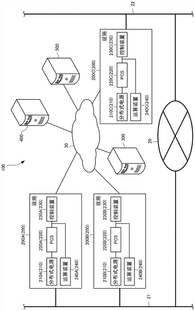
[0027] The power management system according to the embodiment will be described below. like figure 1 As shown, the power management system 100 includes a facility 200 , a power management apparatus 300 , a distribution management apparatus 400 , and a trust server 500 .
[0028] The facilities 200 are connected to each other via the mains power system 20 . The main power system 20 is connected to the power line 21 and the power line 22 . The main power system 20 , the power line 21 , and the power line 22 are power grids that supply power to the facility 200 . Hereinafter, the main power system 20 , the power line 21 , and the power line 22 may be collectively referred to as the power system 20 .
[0029] The facility 200 , the power management apparatus 300 , the distribution management apparatus 400 , and the trust server 500 are connected through the network 30 . The network 30 may include the Internet, and may also include a mobile ...
Deformed example 1
[0138] Modification 1 of the embodiment will be described below. The following mainly describes differences from the embodiments.
[0139] In an embodiment, the predicted value of the output power of the distributed power source 210 is determined through power-related messages received from the facility 200 or the power management device 300 . On the other hand, in Modification 1, the predicted value of the output power of the distributed power source 210 is determined based on the first parameter that affects the output power of the distributed power source 210 .
[0140] Specifically, the distribution management device 400 determines the predicted value of the output power of the distributed power source 210 based on the first parameter. Allocation management apparatus 400 may receive a message from facility 200 including an information element representing the first parameter. The assignment management apparatus 400 may receive a message including an information element i...
Deformed example 2
[0146] Modification 2 of the embodiment will be described below. The following mainly describes differences from the embodiments.
[0147] In an embodiment, the predicted value of the power consumption of the facility 200 is determined by a power-related message received from the facility 200 or the power management apparatus 300 . On the other hand, in Modification 2, the predicted value of the power consumption of the facility 200 is determined based on the second parameter that affects the power consumption of the facility 200 .
[0148] Specifically, the distribution management device 400 specifies the predicted value of the power consumption of the facility 200 based on the second parameter. Allocation management apparatus 400 may receive a message from facility 200 including an information element representing the second parameter. The assignment management apparatus 400 may receive a message including an information element indicating the second parameter from an exte...
PUM
 Abstract
Description
Claims
Application Information
 - R&D
- Intellectual Property
- Life Sciences
- Materials
- Tech Scout
- Unparalleled Data Quality
- Higher Quality Content
- 60% Fewer Hallucinations
Browse by: Latest US Patents, China's latest patents, Technical Efficacy Thesaurus, Application Domain, Technology Topic, Popular Technical Reports.
© 2025 PatSnap. All rights reserved.Legal|Privacy policy|Modern Slavery Act Transparency Statement|Sitemap|About US| Contact US: help@patsnap.com


