
Production process and equipment for corner window glass edge covering assembly

A technology for production equipment and window glass, which is applied in the production process and equipment field of corner window glass edging assembly, which can solve the problems of high maintenance cost, large volume and complex structure of injection molding synthesis equipment, and achieve high production efficiency and Quality, cost savings in production and R&D, and high flexibility

Pending Publication Date: 2022-08-05
GUANGZHOU XINQIANG AUTOMOTIVE COMPONENTS CO LTD
View PDF0 Cites 0 Cited by
  • Summary
  • Abstract
  • Description
  • Claims
  • Application Information

AI Technical Summary

Problems solved by technology

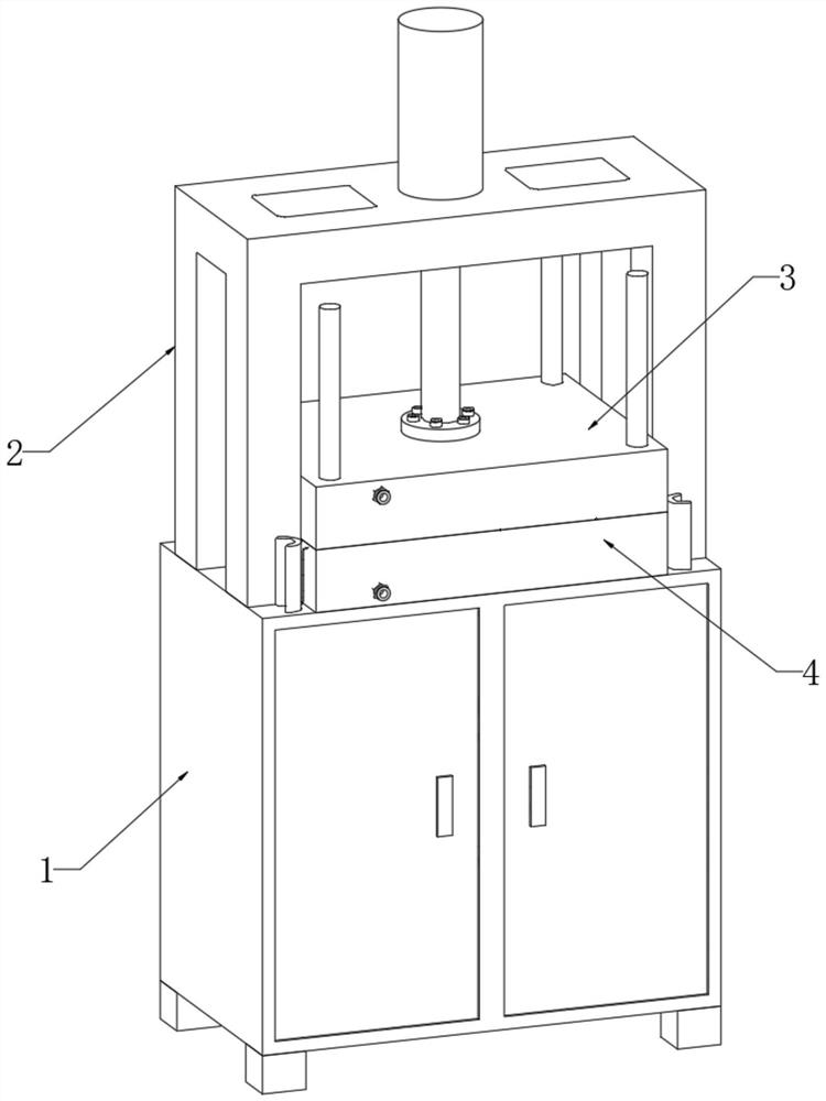
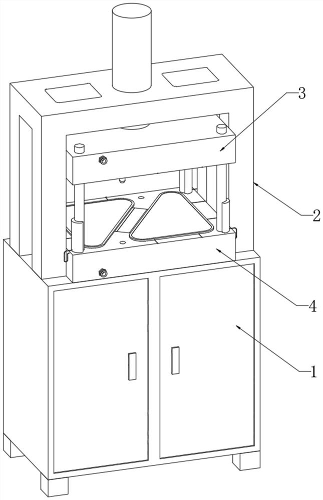
[0003] At present, the mainstream of automobile corner window glass on the market is wrapped with rubber material. The general processing flow is to put the corner window glass into the injection mold, inject glue directly to the edge of the corner window glass after the mold is closed, and wait for the rubber to cool. After forming, the mold is opened and the product is taken out. The production process of this process is relatively simple, but the injection molding synthesis equipment used is bulky and complex in structure, and the cost of equipment maintenance is high. The rubber raw materials need to be melted at high temperature, extruded and injected, and vulcanized. Shape and other processes, so the use of rubber materials to wrap corner window glass determines the cost of production equipment, and thermoplastic silicone only needs to be heated, which is an ideal alternative material, so we propose a corner window wrapped with silicone Window glass and related process equipment

Method used


Image

  • Production process and equipment for corner window glass edge covering assembly
  • Production process and equipment for corner window glass edge covering assembly
  • Production process and equipment for corner window glass edge covering assembly

Examples


Embodiment Construction

[0041] The technical solutions of the present invention will be clearly and completely described below with reference to the accompanying drawings. In the description of the present invention, it should be noted that the terms "center", "upper", "lower", "left", "right", "vertical", "horizontal", "inner", "outer", etc. The indicated orientation or positional relationship is based on the orientation or positional relationship shown in the accompanying drawings, which is only for the convenience of describing the present invention and simplifying the description, rather than indicating or implying that the indicated device or element must have a specific orientation or a specific orientation. construction and operation, and therefore should not be construed as limiting the invention. Furthermore, the terms "first", "second", and "third" are used for descriptive purposes only and should not be construed to indicate or imply relative importance.

[0042] In the description of the...


PUM


Abstract

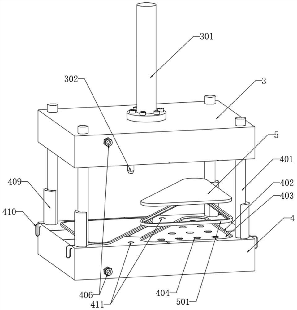
The invention discloses a production process and equipment of a corner window glass edge covering assembly, relates to the field of automobile corner window glass production processes, and provides the following scheme aiming at the problems that the existing injection molding synthesis equipment used for automobile corner window glass is large in size, complex in structure and high in use and maintenance cost: the corner window glass edge covering assembly comprises triangular glass and edge strips, the mold mechanism is used for synthesizing the triangular glass and the edgings, the mold mechanism comprises a rack, an upper mold and a lower mold, the rack is installed at the top end of the equipment cabinet, and the upper mold and the lower mold are connected into the rack in a sleeved mode; a die cavity is formed in the top end of the lower die, a base plate is connected into the die cavity in a sleeved mode, round holes are evenly formed in the base plate, and an air channel is formed in the lower die. The automobile corner window edge covering production process and the mold equipment are novel in structure, the production efficiency and the product quality are optimized, meanwhile, the equipment structure is simple, operation is convenient and fast, and the production cost is low.

Description

technical field [0001] The invention relates to the field of production technology of automobile corner window glass, in particular to a production technology and equipment of a corner window glass edging assembly. Background technique [0002] Car corner glass is generally used in the rear position of the sedan. Conventional cars are not designed to install the lifting or opening and closing structure of the corner glass. The corner glass is directly sealed and fixed to the car body. The installation method of the car corner glass There are two main types, one is to directly bond the corner window glass to the car body after applying sealant along the edge of the corner window glass, and the other is to use the sealing material diagonal window glass package when producing the corner window glass. The edge is connected to the car body through the card slot during installation, and the edge wrapping material of the corner window glass is used to achieve the purpose of sealing...

Claims


Application Information

Patent Timeline
IPC IPC(8): B29C45/14B29C45/34B29C45/43B29K85/00B29K709/08B29L31/30
CPCB29C45/14065B29C45/14008B29C45/34B29C45/43B29C45/0001B29C2045/14155B29K2085/00B29K2709/08B29L2031/3052Y02P40/57
Inventor 詹绍谈龚志业王艳芳李宏兴王有强雷宁毛荣学
Owner GUANGZHOU XINQIANG AUTOMOTIVE COMPONENTS CO LTD
Learn More