Fabricated partition wall mounting structure and mounting method thereof

A technology for installing structures and partition walls, applied in the direction of walls, building components, building structures, etc., can solve the problems of unfavorable connection between curtain wall panels and steel structure skeletons and wooden skeletons. The position of the wooden skeleton, the inability of the air nails to maintain a vertical straight line, etc., can improve the installation efficiency and stability, improve the neatness and accuracy, and improve the firmness.

Pending Publication Date: 2022-08-05
临沂职业学院 +1
0 Cites 0 Cited by

AI-Extracted Technical Summary

Problems solved by technology

[0003] In the prior art, the steel frame is often fixed on the top of the wall and the ground, and then the wooden frame is fixed on the steel frame, and finally the curtain wall panels are fixed on the steel frame and the wooden frame with air nails. However, in the prior art, when the curtain wall panels are installed and fixed, the curtain wall panels are likely to block the view of the construction personnel, making it difficult for the construction personnel to see the positions of the steel structure skeleton and the wooden skeleton, which leads to the failure of the curtain wall panels to be better. The gro...

Method used

[0039] The assembly partition wall installation structure provided by the disclosed embodiment can first intercept the steel structure skeleton 11 and the wooden skeleton 12 that meet the requirements according to the construction requirements, and then insert the wooden skeleton 12 into the embedding on the steel structure skeleton 11 In the groove 13, the steel structure skeleton 11 and the wooden skeleton 12 are installed and combined, and the fixing seat 2 is installed and fixed on the top of the wall and the ground correspondingly, and then the multiple steel structure skeletons 11 and the wooden skeleton 12 after the installation and combination are installed Between the two fixing seats 2, after placing the curtain wall panel 1 on the steel frame 11, place the magnetic auxiliary installation assembly 3 on the curtain wall panel 1, and then move the magnetic auxiliary installation assembly 3 to the steel frame 11 position, the magnetic auxiliary installation component 3 will be adsorbed on the outer surface of the curtain wall panel 1 through the magnet 32, so that the user can drive the air nails along the perforated groove 31 on the magnetic auxiliary installation component 3, which can improve the air nails. The accuracy of the insertion reduces the amount of air nails used and improves installation efficiency; after the air nails are driven into the wooden frame 12, they will bend in rigid contact with the steel structure frame 11, which can further improve the fixing effect of the air nails on the curtain wall panel 1. Firmness, which is conducive to improving the orderliness and accuracy of the air nails, and can improve the installation efficiency and stability of the curtain wall panel 1. At the same time, the connection method of the steel structure skeleton 11 combined with the wooden skeleton 12 is conducive to improving The supporting force further ensures the stability of the overall structure of the prefabricated partition wall.
[0041] Optionally, the thickness of the wooden skeleton 12 is the same as the depth of the embedding groove 13, and the width of the wooden skeleton 12 is the same as the opening width of the embedding groove 13. In this way, the wooden skeleton 12 can be better embedded in the embedding groove 13 on the steel structure skeleton 11, so that after the wooden skeleton 12 is embedded in the embedding groove 13, the side of the steel structure skeleton 11 facing the curtain wall panel 1 can be kept flush, which is convenient The side of the steel structure frame 11 is attached to the side of the curtain wall panel 1, so that the curtain wall panel 1 can be better installed and fixed with the steel structure frame 11 after the air nails are driven in, which is conducive to improving the installation stability of the curtain wall panel 1 .
[0043] Optionally, the perforated slot 31 is a circular structure, and there are a plurality of them arranged at intervals along the length direction of the magnetic auxiliary mounting assembly 3 . In this way, the air nails can be driven into the air nails sequentially through a plurality of punching grooves 31, and after the driving is completed, slide the magnetic suction auxiliary installation assembly 3 to the next driving position, and then drive the air nails through the punching grooves 31 successively, thereby having It is beneficial to improve the orderliness and accuracy of air nailing, and at the same time, with the assistance of the magnetic auxiliary installation assembly 3, the efficiency of air nailing can also be improved, which in turn is beneficial to the installation and fixing efficiency of the curtain wall panel 1 .
[0047] Optionally, the first connection assembly 1-1 includes: a plug 6. There are two groups of bolts 6, and the two groups of bolts 6 are respectively located on both ends of the fixing seat 2, one end of the bolt 6 is fixedly connected with the fixing seat 2, and the other end can be inserted into the side plate 4. In this way, the plugs 6 at both ends of the fixing seat 2 on the top of the wall can be inserted into the tops of the two side plates 4 respectively, and the plugs 6 at both ends of the fixing seat 2 on the ground can be inserted into the bottom ends of the two side plates 4 , so that the two side panels 4 can be more firmly installed on both sides of the curtain wall panel 1, which is conducive to improving the support of the two side panels 4 to the fixing seat 2, and further improving the installation stability of the overall structure of the prefabricated partition wall At the same time, the side plate 4 and the fixing seat 2 can be quickly assembled and fixed by plugging, which is beneficial to improving the installation efficiency of the prefabricated partition wall.
[0048] Optionally, the upper and lower ends of the side plate 4 are respectively provided with a limit groove 8, and the limit groove 8 and the latch 6 are fitted. In this way, the pins 6 on both ends of the fixing seat 2 can be inserted into the limit groove 8, which can prevent the side plate 4 from shaking, thereby helping to improve the support on both sides of the prefabricated partition wall, and can improve the installation of the prefabricated partition wall. stability.
[0049] Optionally, the latch 6 is made up of two boards 61, a slot 62 is provided between the two boards 61, and the upper and lower ends of the side plate 4 are set to an I-shaped structure. In this way, it is convenient for the side plate 4 of the I-shaped structure to be inserted into the slot 62, so that the limit groove 8 is fitted with the latch 6, and the installation and fixation of the side plate 4 is realized, which is conducive to improving the installation efficiency and installation efficiency of the side plate 4. stability.
[0050] Optionally, a plurality of limit grooves 8 are provided, and the plurality of limit grooves 8 are located on the side walls of the upper and lower ends of the side plate 4, respectively. In this way, it is beneficial to make the upper end and the lower end of the side plate 4 form an I-shaped structure, so that the upper end and the lower end of the side plate 4 can be inserted into the latch 6 in the fixing seat 2 on the top of the wall and inserted into the fixing seat on the ground respectively. 2 inside the latch 6 to realize the installation and fixation of the side plate 4, which is conducive to improving the stability of the installation of the side plate 4.
[0051] Optionally, the second connection assembly 2-2 includes: a fixed bump 10. The fixing protrusions 10 are fixedly connected inside the fixing seat 2 , and there are multiple groups of the fixing protrusions 10 , which can be inserted into both ends of the steel structure skeleton 11 . In this way, multiple sets of fixing lugs 10 are arranged in the fixing seat 2, and the fixing lugs 10 can be inserted into the two ends of the steel structure skeleton 11, which is beneficial to combine and install the steel structure skeleton 11 and the wooden skeleton. 12 is installed and fixed between the two fixing seats 2, so that it is convenient to fix the curtain wall panel 1 on the steel structure frame 11 and the wooden frame 12, which is conducive to quick assembly and fixing, and can also improve the steel structure frame 11 and the wooden frame 12. the stability of the installation.
[0052] Optionally, the fixed seat 2 is arranged in a rectangular structure, ...

Abstract

The invention relates to the technical field of assembly type partition walls, and discloses an assembly type partition wall mounting structure which comprises a curtain wall plate, side plates, a framework assembly and a magnetic attraction auxiliary mounting assembly. The number of the curtain wall plates is two, and fixing bases are arranged at the top ends and the bottom ends of the two curtain wall plates. The side plates are arranged in pairs, the two side plates are arranged on the left side and the right side of the curtain wall plate correspondingly, and the fixing base and the side plates are attached to the curtain wall plate correspondingly. The multiple framework assemblies are arranged between the two curtain wall plates, each framework assembly comprises a steel structure framework and a wood framework, an embedding groove is formed in the steel structure framework, and the wood framework and the embedding groove are embedded and arranged in a sliding mode; the magnetic attraction auxiliary installation assembly is in a long strip shape, a punching groove is formed in the middle of the magnetic attraction auxiliary installation assembly, and magnets are arranged on the two side edges of the punching groove and can be attracted to the steel structure framework. In the application, the installation efficiency and stability of the curtain wall plate can be improved, and the use amount of air nails is reduced. The invention further discloses a mounting method of the fabricated partition wall.

Application Domain

WallsBuilding material handling

Technology Topic

PhysicsMagnet +5

Image

  • Fabricated partition wall mounting structure and mounting method thereof
  • Fabricated partition wall mounting structure and mounting method thereof
  • Fabricated partition wall mounting structure and mounting method thereof

Examples

  • Experimental program(1)

Example Embodiment

[0030] In order to understand the features and technical contents of the embodiments of the present disclosure in more detail, the implementation of the embodiments of the present disclosure will be described in detail below with reference to the accompanying drawings, which are for reference only and are not intended to limit the embodiments of the present disclosure. In the following technical description, for the convenience of explanation, numerous details are provided to provide a thorough understanding of the disclosed embodiments. However, one or more embodiments may be practiced without these details. In other instances, well-known structures and devices may be shown simplified in order to simplify the drawings.
[0031] The terms "first", "second" and the like in the description and claims of the embodiments of the present disclosure and the above-mentioned drawings are used to distinguish similar objects, and are not necessarily used to describe a specific order or sequence. It should be understood that the data so used may be interchanged under appropriate circumstances for the purposes of implementing the embodiments of the disclosure described herein. Furthermore, the terms "comprising" and "having", and any variations thereof, are intended to cover non-exclusive inclusion.
[0032] In the embodiments of the present disclosure, the orientations or positional relationships indicated by the terms "upper", "lower", "inner", "middle", "outer", "front", "rear", etc. are based on the orientations shown in the drawings or Positional relationship. These terms are primarily used to better describe the embodiments of the present disclosure and embodiments thereof, and are not intended to limit the fact that the indicated device, element, or component must have a particular orientation, or be constructed and operated in a particular orientation. In addition, some of the above-mentioned terms may be used to express other meanings besides orientation or positional relationship. For example, the term "on" may also be used to express a certain attachment or connection relationship in some cases. For those of ordinary skill in the art, the specific meanings of these terms in the embodiments of the present disclosure can be understood according to specific situations.
[0033] In addition, the terms "arranged", "connected" and "fixed" should be construed broadly. For example, "connection" may be a fixed connection, a detachable connection, or a unitary construction; it may be a mechanical connection, or an electrical connection; it may be a direct connection, or an indirect connection through an intermediary, or two devices, elements or Internal connectivity between components. For those of ordinary skill in the art, the specific meanings of the above terms in the embodiments of the present disclosure can be understood according to specific situations.
[0034] Unless stated otherwise, the term "plurality" means two or more.
[0035] In the embodiment of the present disclosure, the character "/" indicates that the preceding and following objects are in an "or" relationship. For example, A/B means: A or B.
[0036] The term "and/or" is an associative relationship describing objects, indicating that three relationships can exist. For example, A and/or B, means: A or B, or, A and B three relationships.
[0037] It should be noted that the embodiments in the embodiments of the present disclosure and the features in the embodiments may be combined with each other in the case of no conflict.
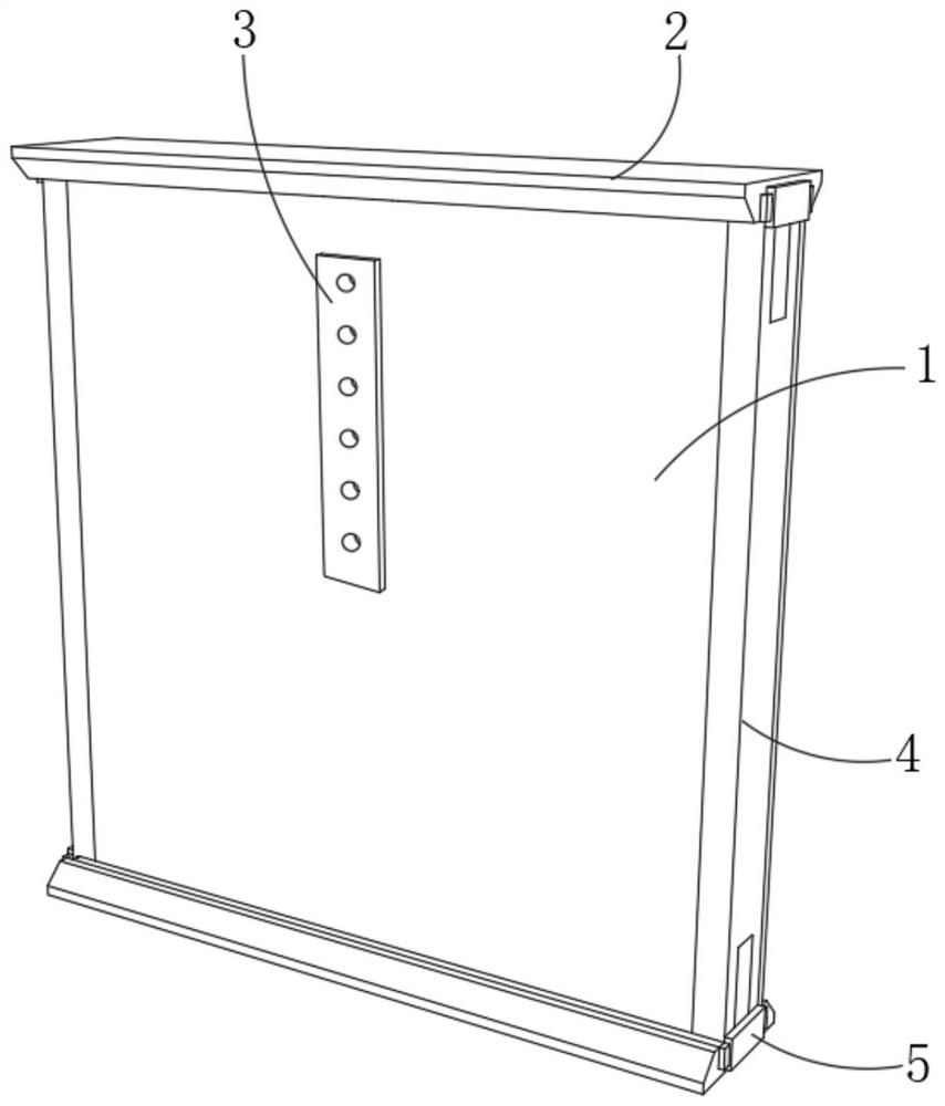
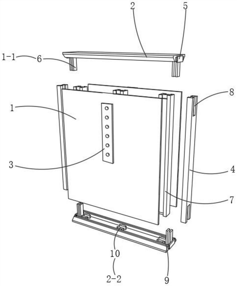
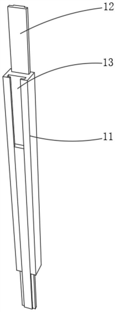
[0038] combine Figure 1-4 As shown, the embodiment of the present disclosure provides a prefabricated partition wall installation structure, including: a curtain wall panel 1 , a side panel 4 , a frame assembly 7 and a magnetic auxiliary installation assembly 3 . There are two curtain wall panels 1, and the top and bottom ends of the two curtain wall panels 1 are provided with fixed seats 2; , the fixed seat 2 and the side panel 4 are respectively attached to the curtain wall panel 1; there are multiple skeleton components 7, and the multiple skeleton components 7 are arranged between the two curtain wall panels 1, and the skeleton component 7 includes a steel structure skeleton 11 and wood The skeleton 12 and the steel structure skeleton 11 are provided with an embedded groove 13, and the wooden skeleton 12 is fitted with the embedded groove 13 and slides; Magnets 32 are arranged on both sides of the 31 , and the magnets 32 can be adsorbed on the steel structure frame 11 .
[0039]Using the prefabricated partition wall installation structure provided by the embodiment of the present disclosure, the steel structure skeleton 11 and the wooden skeleton 12 that meet the requirements can be intercepted first according to the construction requirements, and then the wooden skeleton 12 can be inserted into the embedding groove 13 on the steel structure skeleton 11 , install and combine the steel structure skeleton 11 and the wooden skeleton 12, further install and fix the fixed seat 2 on the top of the wall and the ground, and then install the assembled steel structure skeleton 11 and the wooden skeleton 12 on the two Between the fixed bases 2, after placing the curtain wall panel 1 on the steel structure frame 11, place the magnetic suction auxiliary installation component 3 on the curtain wall panel 1, and then move the magnetic suction auxiliary installation component 3 to the position of the steel structure frame 11, The magnetic suction auxiliary installation component 3 will be adsorbed on the outer side of the curtain wall panel 1 through the magnet 32, so that the user can drive the air nails along the punching slot 31 on the magnetic suction auxiliary installation component 3, which can improve the accuracy of driving the air nails It can reduce the usage of air nails and improve the installation efficiency; after the air nails are driven into the wooden frame 12, they will be bent in rigid contact with the steel structure frame 11, which can further improve the firmness of the air nails to the curtain wall panel 1. Therefore, it is beneficial to not only improve the neatness and accuracy of driving the air nails, but also improve the installation efficiency and stability of the curtain wall panel 1. At the same time, the connection method of the steel structure frame 11 and the wooden frame 12 is adopted, which is beneficial to improve the supporting force. It further ensures the stability of the overall structure of the prefabricated partition wall.
[0040] Optionally, the thickness of the wooden frame 12 and the depth of the embedded groove 13 are smaller than the length of the air nail. In this way, after the air nail is driven into the wooden frame 12, it will bend when encountering the steel structure frame 11, and the wooden frame 12 can be hooked, which is beneficial to improve the installation stability of the air nail to the curtain wall panel 1 and avoid the curtain wall Plate 1 shakes.
[0041] Optionally, the thickness of the wooden frame 12 is the same as the depth of the embedding groove 13 , and the width of the wooden frame 12 is the same as the opening width of the embedding groove 13 . In this way, the wooden frame 12 can be better embedded in the embedding groove 13 on the steel structure frame 11, so that after the wooden frame 12 is embedded in the embedding groove 13, the side of the steel structure frame 11 facing the curtain wall panel 1 can be kept flush, which is convenient for The side of the steel structure frame 11 is attached to the side of the curtain wall panel 1, so that the curtain wall panel 1 can be better installed and fixed with the steel structure frame 11 after the air nails are driven, which is beneficial to improve the installation stability of the curtain wall panel 1. .
[0042] Optionally, the width of the auxiliary magnetic installation assembly 3 is the same as the width of the steel structure skeleton 11 . In this way, the magnets 32 disposed on both sides of the punching slot 31 can be better attracted to the steel structure skeleton 11, so that the magnetic attraction auxiliary installation assembly 3 can be moved along the length direction of the steel structure skeleton 11 to make the punching The holes 31 can be located at different positions, and then the air nails are driven one by one through the punching grooves 31, which is beneficial to improve the driving efficiency and the driving accuracy of the gas nails.
[0043] Optionally, the perforated slots 31 are of circular structure, and are provided with a plurality of them, and are arranged at intervals along the length direction of the auxiliary magnetic attraction mounting assembly 3 . In this way, the air nails can be driven in sequence through the plurality of punching grooves 31, and after the driving is completed, slide the magnetic suction auxiliary installation assembly 3 to the next driving position, and then drive the air nails through the punching grooves 31 in sequence. It is beneficial to improve the neatness and accuracy of driving the air nails, and at the same time, the efficiency of driving the air nails can be improved with the assistance of the magnetic suction auxiliary installation component 3 , thereby facilitating the installation and fixing efficiency of the curtain wall panel 1 .
[0044] Optionally, the hole diameter of the punching slot 31 is larger than the diameter of the other end opposite the driving end of the air nail. In this way, after driving the air nails, it is possible to prevent the other end of the air nails from being nailed on the auxiliary magnetic installation component 3, so that the auxiliary magnetic installation component 3 is fixed on the curtain wall panel 1, which is beneficial to the auxiliary magnetic installation. The sliding of the assembly 3 can further slide the magnetic suction auxiliary installation assembly 3 to the next installation position after the air nail is driven, and drive the air nail through the punching slot 31 .
[0045] Optionally, a first connecting assembly 1-1 and a second connecting assembly 2-2 are provided inside the fixing base 2, and the first connecting assembly 1-1 is arranged on both ends of the fixing base 2 for fixing two side plates. 4; the second connecting assembly 2-2, which is provided with a plurality of and located inside the fixing seat 2, is used for fixing the steel structure frame 11. In this way, the combined steel structure frame 11 can be fixedly installed inside the fixing base 2 through a plurality of second connecting components 2-2, so that the steel structure frame 11 and the wooden frame 12 can be installed between the two fixing bases 2, and then The two side panels 4 are installed and fixed at the two ends of the fixed seat 2 by the first connecting assembly 1-1, and the two sides of the curtain wall panel 1 are blocked, thereby helping to improve the stability of the overall structure of the prefabricated partition wall.
[0046] Optionally, the plurality of second connection assemblies 2-2 are spaced apart from each other. In this way, after the steel structure frame 11 and the wooden frame 12 are installed and combined, they can be installed and fixed on the fixed seat 2 at intervals through the second connecting components 2-2, which is beneficial to improve the fixed support area of ​​the steel structure frame 11 to the curtain wall panel 1. Further, the installation stability of the curtain wall panel 1 can be improved, and the shaking of the curtain wall panel 1 can be avoided.
[0047] Optionally, the first connection component 1 - 1 includes: a plug 6 . There are two sets of plugs 6 , and the two sets of plugs 6 are respectively located on both ends of the fixing base 2 . One end of the plugs 6 is fixedly connected with the fixing base 2 , and the other end can be inserted into the side plate 4 . In this way, the pins 6 at both ends of the fixing base 2 on the top of the wall can be inserted into the top ends of the two side panels 4 respectively, and the plugs 6 at both ends of the fixing base 2 on the ground can be inserted into the bottom ends of the two side panels 4 , so that the two side panels 4 can be more stably installed on both sides of the curtain wall panel 1, which is beneficial for the two side panels 4 to improve the support of the fixed seat 2, and further improves the installation stability of the overall structure of the prefabricated partition wall. At the same time, the side plate 4 and the fixing seat 2 can be quickly assembled and fixed by means of plugging, which is beneficial to improve the installation efficiency of the prefabricated partition wall.
[0048] Optionally, the upper and lower ends of the side plate 4 are respectively provided with limiting slots 8 , and the limiting slots 8 are fitted with the latches 6 . In this way, the pins 6 on the two ends of the fixed seat 2 can be inserted into the limiting grooves 8, which can prevent the side plate 4 from shaking, which is beneficial to improve the support on both sides of the prefabricated partition wall, and can improve the installation of the prefabricated partition wall. stability.
[0049] Optionally, the plug 6 is composed of two plug boards 61, a plug slot 62 is provided between the two plug boards 61, and the upper and lower ends of the side plate 4 are set in an I-shaped structure. In this way, it is convenient for the side plate 4 of the I-shaped structure to be inserted into the insertion slot 62, so that the limiting groove 8 is fitted with the plug 6 to realize the installation and fixation of the side plate 4, which is beneficial to improve the installation efficiency and installation of the side plate 4. stability.
[0050] Optionally, a plurality of limiting grooves 8 are provided, and the plurality of limiting grooves 8 are respectively located on the two side walls of the upper end and the lower end of the side plate 4 . In this way, it is beneficial to form an I-shaped structure on the upper and lower ends of the side plate 4, so that the upper and lower ends of the side plate 4 can be inserted into the bolts 6 in the fixed seat 2 on the top of the wall and into the fixed seat on the ground respectively. In the plug 6 in the 2, the installation and fixation of the side plate 4 is realized, which is beneficial to improve the installation stability of the side plate 4.
[0051] Optionally, the second connection component 2 - 2 includes: a fixing bump 10 . The fixing bumps 10 are fixedly connected inside the fixing base 2 , and there are multiple sets of the fixing bumps 10 , which can be inserted into both ends of the steel structure frame 11 . In this way, by arranging a plurality of sets of fixing projections 10 in the fixing seat 2, and enabling the fixing projections 10 to be inserted into the two ends of the steel structure frame 11, it is beneficial to install the steel structure frame 11 and the wooden frame in combination with a plurality of groups. 12 is installed and fixed between the two fixing bases 2, so that the curtain wall panel 1 can be easily fixed on the steel structure frame 11 and the wooden frame 12, which is conducive to quick assembly and fixing, and can also improve the steel structure frame 11 and the wooden frame 12. installation stability.
[0052] Optionally, the fixing base 2 is provided in a rectangular structure, and multiple groups of fixing bumps 10 are arranged along the length direction of the fixing base 2 , and the multiple sets of fixing bumps 10 are spaced from each other. In this way, a plurality of combined steel structure skeletons 11 can be sequentially installed and fixed on the fixed seat 2 through the fixing bumps 10, so that there is an installation space between each steel structure skeleton 11, which is beneficial to improve the effect of the steel structure skeleton 11 on the curtain wall panel. 1 support area, improve the installation stability of the curtain wall panel 1.
[0053] Optionally, the fixing bumps 10 are fitted into the embedding grooves 13 . In this way, the embedded grooves 13 on the steel structure skeleton 11 can be quickly butt-fixed with the fixing bumps 10, and the embedded grooves 13 can provide limit fixation at both ends of the steel structure skeleton 11, so that the steel structure skeleton 11 can be fixed between the two Between the fixed bases 2 , it is beneficial to improve the installation stability of the steel structure frame 11 .
[0054] Optionally, there are two fixing bumps 10 in each group, and the two fixing bumps 10 are symmetrically arranged on the fixing base 2 . In this way, it is convenient for the embedding groove 13 to be fitted with the fixing protrusions 10, which is beneficial to improve the neatness of the installation and fixing of the steel structure skeleton 11, and at the same time, it is convenient to quickly install the two steel structure skeletons 11 through the two identical fixing protrusions 10. It is beneficial to save installation time and improve installation efficiency.
[0055] It can be understood that, after the steel structure skeleton 11 is butt-installed with the fixing projections 10 , a transverse connecting beam (not shown in the figure) may be further installed between each steel structure skeleton 11 . In this way, through the cooperation between the steel structure skeleton 11 and the transverse connecting beams, the steel structure skeleton 11 can be prevented from shaking, and the firmness of the steel structure skeleton 11 to support and fix the curtain wall panel 1 can be improved.
[0056] combine Figure 5 As shown, in some embodiments, optionally, the prefabricated partition wall installation structure further includes: a caulking board 9 . The caulking plate 9 is arranged inside the fixing base 2 , and the caulking plate 9 is rotatably connected with the fixing base 2 . In this way, the caulking plate 9 can be rotated to the inside of the fixed seat 2 and be parallel to the fixed seat 2, and the two ends of the steel structure frame 11 installed in the fixed seat 2 can be squeezed to prevent the steel structure frame 11 from shaking. Therefore, it is beneficial to further improve the installation stability of the steel structure frame 11 .
[0057] Optionally, a groove 201 is provided inside the fixing base 2, a connecting shaft (not shown in the figure) is provided at both ends of the fixing base 2, and one end of the connecting shaft is fixedly connected with the inner wall of the groove 201, and the other end passes through the groove 201. Set in one end of the caulking plate 9, the caulking plate 9 can be rotated on the connecting shaft. In this way, the caulking plate 9 can be rotated on the fixed seat 2, so that when the steel structure frame 11 is installed, the caulking plate 9 can be rotated to be perpendicular to the fixed seat 2, and the effect of the caulking plate 9 on the steel structure frame can be avoided. The installation of 11 causes obstacles. At the same time, after the steel structure skeleton 11 is installed, control the caulking plate 9 to rotate into the fixed seat 2, so that the side of the caulking plate 9 in the length direction is in contact with the side of the steel structure skeleton 11, thereby The steel structure skeleton 11 can be squeezed and fixed to avoid shaking of the steel structure skeleton 11 , which is beneficial to improve the installation stability of the steel structure skeleton 11 .
[0058] Optionally, the caulking plates 9 are arranged in pairs, and are respectively located on both sides of the fixing base 2 in the length direction. In this way, the two steel structure skeletons 11 on the fixing base 2 can be squeezed and fixed by the two caulking plates 9 , which is beneficial to improve the installation stability of the steel structure skeleton 11 .
[0059] Optionally, the two caulking plates 9 are respectively located on both sides of the fixing bump 10 . In this way, the rotation of the caulking plate 9 is facilitated, and the rotation of the caulking plate 9 is prevented from being hindered by the fixed protrusions 10 .
[0060] Optionally, one side of the caulking plate 9 in the longitudinal direction is attached to the side of the steel structure skeleton 11 . In this way, the caulking plate 9 can be in better contact with the steel structure skeleton 11, and the steel structure skeleton 11 can be squeezed and fixed, which can prevent the steel structure skeleton 11 from shaking after installation and fixing, which is beneficial to improve the steel structure skeleton 11. installation stability.
[0061]Optionally, the left and right sides of the fixing base 2 are respectively provided with fixing assemblies 5 , and the fixing assemblies 5 include: a sleeve 14 and a movable block 15 . The sleeve 14 is fixedly connected with the fixed seat 2 ; the movable blocks 15 are provided with two groups, and the two groups of movable blocks 15 are respectively arranged inside the sleeve 14 and are slidably arranged with the sleeve 14 . In this way, when installing the steel structure skeleton 11, the movable block 15 can be slid out of the sleeve 14 first, and then the caulking plate 9 can be controlled to rotate to a position perpendicular to the fixed seat 2, and after the steel structure skeleton 11 is installed and fixed After that, the caulking plate 9 is rotated to the initial position, and finally, by sliding the movable block 15 into the sleeve 14, the end faces of the caulking plate 9 are squeezed and fixed at both ends of the fixed seat 2, which is conducive to improving the The stability of the caulking plate 9 enables the caulking plate 9 to more stably press and fix the upper and lower ends of the steel structure skeleton 11 , which can further improve the installation stability of the steel structure skeleton 11 .
[0062] Optionally, the two groups of movable blocks 15 are respectively fitted with the two groups of caulking boards 9 . In this way, it is beneficial to make the movable block 15 better contact the end face of the caulking plate 9, and to press and fix the caulking plate 9 to prevent the caulking plate 9 from shaking, and at the same time, it is also beneficial to avoid the caulking plate 9 The two ends block the sliding of the movable block 15, so that the movable block 15 can slide in the sleeve 14, so that the caulking plate 9 can be better controlled to rotate and disengage from the side of the steel structure skeleton 11, which is convenient for the steel structure skeleton. 11 for disassembly.
[0063] It is worth noting that, in the assembled partition wall installation structure provided by the embodiment of the present disclosure, a groove 201 may be provided in the fixing seat 2 , or the top surface of the fixing seat 2 may be set as a smooth surface, inside the fixing seat 2 When the grooves 201 are provided, the curtain wall panel 1 can be further fixed by combining and installing a plurality of steel structure skeletons 11 and wooden skeletons 12, and then fixing the combined steel structure skeleton 11 between the two fixing seats 2. On the steel structure skeleton 11, the two side panels 4 are then fixed on both sides of the curtain wall panel 1, so as to complete the splicing of a single assembly structure of the prefabricated partition wall, and so on, splicing a plurality of single assembly structures one by one, and finally A plurality of assembled and fixed curtain wall panels 1 are spliced ​​and fixed, so as to realize the modular assembly and fixation of the prefabricated partition wall.
[0064] Further, when the top surface of the fixed base 2 is set to be a smooth surface, a fixed base 2 can be fixed on the top of the wall and the ground respectively, and then the combined whole steel structure skeleton 11 is slid into the two fixed bases 2. so that a plurality of combined steel structure frames 11 can be sequentially slid between the two fixing seats 2, and then the curtain wall panel 1 is fixed on the steel structure frame 11, and the two side panels 4 are fixed on the curtain wall. On both sides of the board 1, the overall structure of the prefabricated partition wall is installed and fixed. In this way, different assembling and fixing methods can be selected according to the actual installation requirements of the prefabricated partition wall, which is beneficial to improve the installation efficiency of the prefabricated partition wall.
[0065] combine Image 6 As shown, an embodiment of the present disclosure provides a method for installing a prefabricated partition wall, including the following steps:
[0066] S01, according to the construction requirements, intercept the steel structure skeleton and the wooden skeleton that meet the requirements, and insert the wooden skeleton into the embedding groove on the steel structure skeleton;
[0067] S02, connect the steel structure skeletons according to the construction requirements, and fix them between the ground and the roof;
[0068] S03, attach the curtain wall panel from the lower side of the steel structure skeleton;
[0069] S04, place the magnetic suction auxiliary installation component on one side of the curtain wall panel, so that it is adsorbed on the steel structure frame across the curtain wall panel;
[0070] S05, use a nail gun to drive nails at a small angle along the punching slot of the magnetic auxiliary installation component;
[0071] S06, move the magnetic attraction auxiliary installation components to nail one by one until the curtain wall panel is completely fixed.
[0072] By using the method for installing the prefabricated partition wall provided by the embodiment of the present disclosure, the steel structure skeleton and the wooden skeleton that meet the requirements can be intercepted according to the construction requirements, and then the wooden skeleton can be inserted into the embedding groove on the steel structure skeleton, so that the steel structure skeleton can be Install and combine with the wooden frame, further install and fix the fixed seat on the top of the wall and the ground, and then install the combined steel structure frame and wooden frame between the two fixed seats, and then place the curtain wall panel. After it is on the steel structure frame, place the magnetic auxiliary installation component on the curtain wall panel, and then move the magnetic auxiliary installation component to the position of the steel structure frame. The air nails can be driven one by one along the magnetic suction auxiliary installation components until the curtain wall panel is completely fixed, which can improve the accuracy of driving the air nails, reduce the use of air nails, and improve the installation efficiency; while the air nails are driven into the wood After the skeleton, it will be bent in rigid contact with the steel structure skeleton, which can further improve the firmness of the air nails to the curtain wall panel, which is beneficial to not only improve the neatness and accuracy of the air nails, but also improve the curtain wall panel. Installation efficiency and stability, and the connection method of steel structure skeleton combined with wooden skeleton is beneficial to improve the supporting force and further ensure the stability of the overall structure of the prefabricated partition wall.
[0073] Optionally, S01, according to the construction requirements, intercept the steel structure skeleton and the wooden skeleton that meet the requirements, and insert the wooden skeleton into the embedding groove on the steel structure skeleton, including:
[0074] Use the measuring tool to measure the distance between the top of the wall and the ground, and calculate the required length of the steel frame and wooden frame according to the distance. In this way, the length of the steel structure skeleton and the wooden skeleton to be cut can be calculated according to the distance between the top of the wall and the ground, which facilitates the assembly and fixing of the cut steel structure skeleton and the wooden skeleton, and can avoid excessive waste. cut costs.
[0075] Understandably, the measuring tool may be a meter ruler, or a measuring tool such as a steel ruler or a tape measure.
[0076] combine Figure 7 As shown, optionally, S01, according to the construction requirements, intercept the steel structure skeleton and the wooden skeleton that meet the requirements, and insert the wooden skeleton into the embedding groove on the steel structure skeleton, including:
[0077] S11, determine the installation position of the prefabricated partition wall, and carry out construction alignment and marking on the top of the wall and the ground;
[0078] S12, install the fixing seat according to the markings on the top of the wall and the ground, and then slide a plurality of combined steel structure frames between the two fixing seats. In this way, it is beneficial to improve the installation accuracy of the prefabricated partition wall, so that the prefabricated partition wall after installation can be more vertical, and the prefabricated partition wall is prevented from tilting.
[0079] It is worth noting that when setting out the construction line on the top of the wall and the ground, you can use the infrared measuring instrument to carry out the construction line out. In this way, the infrared measuring instrument can map the red line on the top of the wall and the ground at the same time, which is conducive to laying out and marking on the top of the wall and the ground at the same time. Vertical, to prevent the steel structure frame from tilting.
[0080] combine Figure 8 As shown, optionally, S03, the curtain wall panel is attached from the lower side of the steel structure frame, including:
[0081] S31, place the bottom end face of the curtain wall panel on the fixed seat to keep the curtain wall panel in a vertical state;
[0082] S32, correct whether the curtain wall panel is located at the installation position, so that one side of the curtain wall panel overlaps with the side edge of the steel structure frame. In this way, the curtain wall panel can be closely attached to the steel structure frame, which is convenient for subsequent nailing and fixing, and at the same time, the curtain wall panel can be prevented from being inclined, and the installation accuracy of the curtain wall panel can be improved.
[0083] combine Figure 9 As shown, optionally, S04, place the magnetic suction auxiliary installation component on one side of the curtain wall panel, so that it is adsorbed on the steel structure frame across the curtain wall panel, including:
[0084] S41, place the magnetic suction auxiliary installation component on the curtain wall panel, and move the magnetic suction auxiliary installation component to find the installation position of the steel structure skeleton;
[0085] S42 , when the magnetic suction auxiliary installation component is stagnant, the rear side of the position of the curtain wall here is the installation position of the steel structure frame, and then the magnetic suction auxiliary installation component is controlled to be vertically adsorbed on the steel structure frame. In this way, it is beneficial to find the installation position of the steel structure skeleton through the magnetic auxiliary installation component, and the magnetic auxiliary installation component is adsorbed on the steel structure skeleton, which is convenient to provide an auxiliary function for the subsequent nailing, and can improve the accuracy of nailing.
[0086] The foregoing description and drawings sufficiently illustrate the embodiments of the present disclosure to enable those skilled in the art to practice them. Other embodiments may include structural and other changes. The examples represent only possible variations. Unless expressly required, individual components and functions are optional and the order of operations may vary. Portions and features of some embodiments may be included in or substituted for those of other embodiments. Embodiments of the present disclosure are not limited to the structures that have been described above and shown in the accompanying drawings, and various modifications and changes may be made without departing from the scope thereof. The scope of the present disclosure is limited only by the appended claims.

PUM

no PUM

Description & Claims & Application Information

We can also present the details of the Description, Claims and Application information to help users get a comprehensive understanding of the technical details of the patent, such as background art, summary of invention, brief description of drawings, description of embodiments, and other original content. On the other hand, users can also determine the specific scope of protection of the technology through the list of claims; as well as understand the changes in the life cycle of the technology with the presentation of the patent timeline. Login to view more.

Similar technology patents

Classification and recommendation of technical efficacy words

  • High precision
  • reduce usage

Method for forecasting short-term power in wind power station

InactiveCN102102626AHigh precision
Owner:NORTH CHINA ELECTRIC POWER UNIV (BAODING) +1

Numerical control machine tool wear monitoring method

InactiveCN102091972AHigh precisionReal-time monitoring of tool wear
Owner:HUAZHONG UNIV OF SCI & TECH +1

Advertisement recommendation method and apparatus

ActiveCN104965890AHigh precisionPrecise screening
Owner:SHENZHEN TENCENT COMP SYST CO LTD

Chitosan oligosaccharide compounded preparation and application in prolonging shelf life of fruits

InactiveCN104642528AExtend fruit shelf lifereduce usage
Owner:DALIAN INST OF CHEM PHYSICS CHINESE ACAD OF SCI

Fish-vegetable symbiotic integration system

InactiveCN103999812Areduce usageSave on bait usage
Owner:姜威毅

Full-color 3D printing device and method

ActiveCN106393662Awide color gamutreduce usage
Owner:SHENZHEN 7TH TECH CO LTD

Medical washing and disinfecting machine

InactiveCN104826144Areduce usageImprove efficiency
Owner:广州涞泊锐科技股份有限公司

Temperature-sensitive color-changing coating

InactiveCN102585674Amaintain a comfortable temperaturereduce usage
Owner:武汉康桥伟业高新科技有限公司
Why Eureka
Try Eureka