Electric pole composite wire drawing device and using method thereof

A technology for pulling wire devices and electric poles, applied in towers, building types, buildings, etc., can solve problems such as loss of tension, rusted and broken wires, weight and corrosion of iron parts, etc., to reduce storage space, increase traction stress, increase The effect of transport capacity

Pending Publication Date: 2022-08-05
CHINA PETROLEUM & CHEM CORP +1
View PDF3 Cites 0 Cited by
  • Summary
  • Abstract
  • Description
  • Claims
  • Application Information

AI Technical Summary

Problems solved by technology

The required assembly process is cumbersome, the construction time is long, the labor intensity is increased, and there is a defect that the iron parts are corroded and broken and lose the tensile force
[0006] The erection site of the power line is basically in an environment with poor road transportation conditions in the field. Due to the heavy weight of the cement cable reel, it is difficult to carry it manually and difficult to move, so a crane must be used to assist in the movement and transportation; It is necessary to pre-embed the iron hanging ring during production. The iron hanging ring is buried in the wet ground, and it often rusts and breaks, making the pull wire useless; in addition, the pull rod connecting the pull wire and the pull wire reel is made of steel material and embedded in the lower half of the pull wire reel. Underground, also often broken due to rust
The above patented technologies all use the method of assembling the cement blocks separately to reduce the weight and improve the cable tray, which does not fundamentally solve the problems of weight and iron parts corrosion

Method used


Image

  • Electric pole composite wire drawing device and using method thereof
  • Electric pole composite wire drawing device and using method thereof
  • Electric pole composite wire drawing device and using method thereof

Examples


Embodiment Construction

[0033] In order to make the purposes, technical solutions and advantages of the embodiments of the present invention clearer, the technical solutions in the embodiments of the present invention will be clearly and completely described below in conjunction with the embodiments of the present invention. Obviously, the described embodiments are part of the present invention. examples, but not all examples. Based on the embodiments of the present invention, all other embodiments obtained by those of ordinary skill in the art without creative efforts shall fall within the protection scope of the present invention.

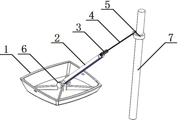
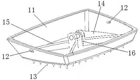
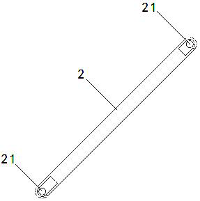
[0034] refer to figure 1 , a composite cable pulling device for an electric pole, comprising a pulling plate 1, a pulling rod 2, a UT wire clamp 3, a steel wire pulling wire 4 and a hoop 5. The plate 11 can be open to the surrounding and hold the soil pressed on it, which increases the traction stress of the pull pulley 1. The pull pulley 1 is connected to the lower en...


PUM


Abstract

The invention discloses an electric pole composite stay wire device which comprises a pull disc, a stay wire rod, a UT wire clamp, a steel wire stay wire and a hoop, after the pull disc is of an open disc-shaped structure, a slope plate can wrap and press soil on the slope plate towards the periphery in an open mode, the traction stress of the pull disc is increased, the pull disc is connected with the lower end of the stay wire rod through a locking plug-in, the UT wire clamp is arranged at the upper end of the stay wire rod, and the steel wire stay wire is arranged at the lower end of the stay wire rod. The UT wire clamp is connected with a hoop through a steel wire stay wire, and the hoop is used for being fixed on an electric pole. The application method comprises the following steps: firstly, determining the position of the pole stay wire and digging the stay wire pit according to requirements; one end of the anchor rod is inserted into the connecting base to be reliably connected and locked; the pull disc is placed at the bottom of the stay wire pit, the higher slope plate side is far away from the electric pole, and the opposite lower slope plate side is close to the electric pole; the stay wire rod and the steel stay wire are fixed; backfilling the stay wire pit with soil, and compacting; and a UT wire clamp is used for connecting and tensioning. The stability of the electric pole is guaranteed, construction is convenient and flexible, the labor intensity is reduced, the construction and storage cost is saved, and the working efficiency is improved.

Description

technical field [0001] The invention relates to the technical field of wire fixing of electric poles of power lines, in particular to a composite wire pulling device for electric poles and a method for using the same. Background technique [0002] In the erection and installation of power lines, a large number of various types of poles need to be used. After the installation of the pole is completed, in order to ensure the stability of the pole and the tension balance of the wire and the lightning protection wire, so that the pole is not affected by the wind and other external factors, the pole cable will be made at the same time as the pole is installed. Stabilize poles to ensure safe operation of power lines. One side of the cable of the pole is connected to the upper side of the pole, and the other side needs to be connected to the cable rod and the cable tray deeply buried in the horizontal ground through the UT clip to cope with the pulling force when the pole falls. ...

Claims


Application Information

Patent Timeline
IPC IPC(8): E04H12/20E04H12/00
CPCE04H12/20E04H12/00
Inventor 马广俊张利邵志宏朱孟宗孙黎新高明华刘清张芸彤贾东
Owner CHINA PETROLEUM & CHEM CORP
Why Eureka
Try Eureka