Self-locking blocking shield TBM construction auxiliary equipment
An auxiliary equipment and shield technology, applied in mining equipment, shaft equipment, shaft lining, etc., can solve the problems of low efficiency and labor consumption, and achieve the effect of high degree of automation, low work intensity, and convenient splicing
- Summary
- Abstract
- Description
- Claims
- Application Information
AI Technical Summary
Problems solved by technology
Method used
Image

Examples
Embodiment 1
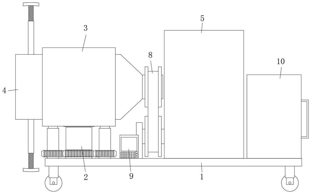
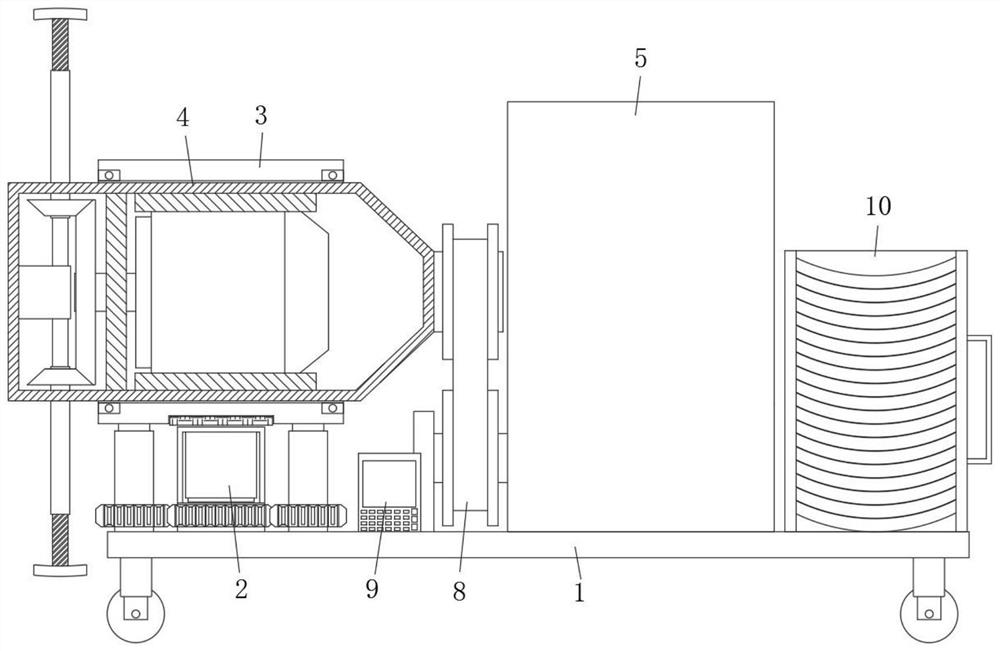
[0036] refer to Figure 1-3And 5-7, a self-locking blocking shield TBM construction auxiliary equipment, including a propulsion trolley 1, driving wheels are installed at the four corners of the bottom surface of the propulsion trolley 1, and a jacking assembly 2 is installed on the front side of the propulsion trolley 1, A drum 3 is fixed at the output end of the jacking assembly 2, and an auxiliary assembly 4 for assisting the assembly of segments is installed in the drum 3. During use, the installation position can be adjusted through the jacking assembly 2, so that the device can adapt to shields of different heights. Tunnel construction requires that after adjustment, the segments are assembled and spliced sequentially through the auxiliary component 4, which is easy to operate, greatly improves the efficiency of shield splicing, and also ensures the quality of segment splicing. The auxiliary component 4 includes a rotating cylinder 41, which rotates The cylinder 41 is ...
Embodiment 2
[0038] like Figure 5-7 As shown, this embodiment is basically the same as Embodiment 1. Preferably, the limit component includes a limit post 49, the outer wall of the limit post 49 is fixed with a limit rod 410, and one end of the limit rod 410 extends to the inner side of the threaded cylinder 1 45, The first end of the threaded cylinder 45 and the threaded rod 1 47 are provided with limiting grooves. The limiting grooves are slidably connected with a rotation blocking rod 411. The blocking rods 411 are fixed at both ends with a limiting piece 412, and a limiting column 49 is fixed on the rotating cylinder. 41 is on the side wall of one end, and the number of limit rods 410 is the same as that of threaded barrel 1 45, the limit groove is arranged in a cylindrical shape, the inner wall of the limit groove is also provided with a strip groove, and the limit pieces 412 are placed in the strip groove. so that the threaded cylinder 1 45 can be rotated while preventing the synchr...
Embodiment 3
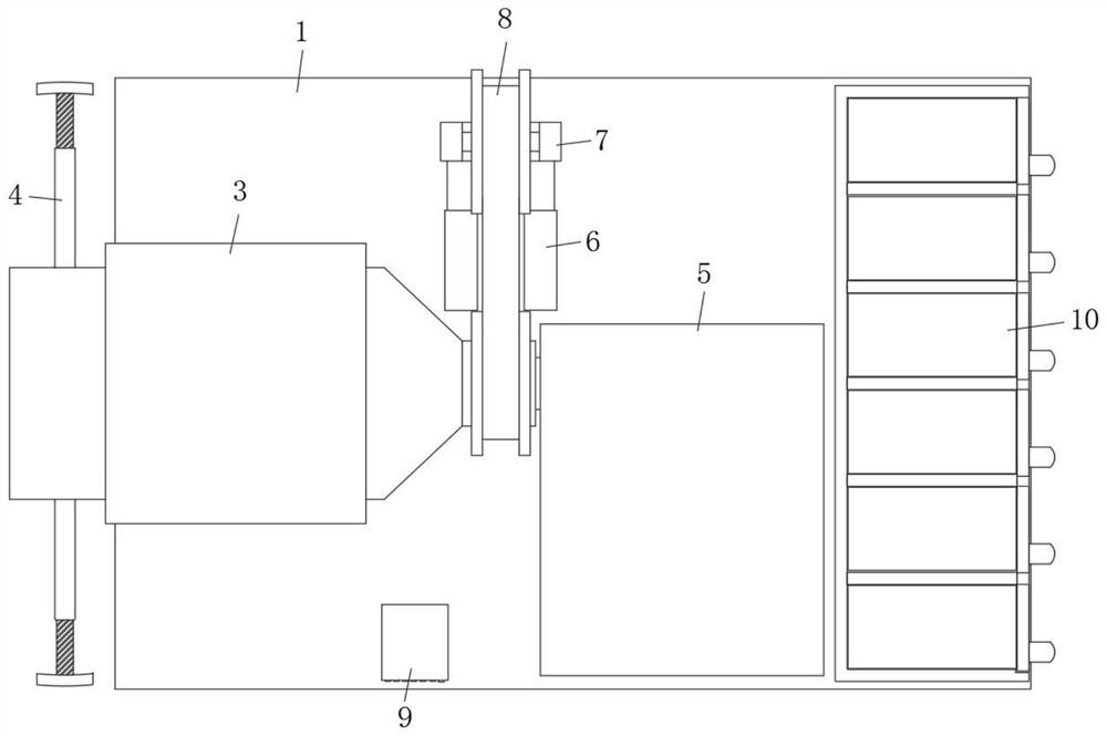
[0041] like figure 2 and 4 As shown, this embodiment is basically the same as Embodiment 1. Preferably, the jacking assembly 2 includes a second threaded barrel 21. The second threaded barrel 21 is provided with four threaded barrels and is rotatably mounted on the top surface of the propulsion trolley 1 in a rectangular shape. The inner walls of the second 21 are connected with threaded rods 22 through threads. The tops of the second threaded rods 22 are fixed on the bottom surface of the drum 3. A rubber cushion 23 is also fixed on the inner side of the middle of the bottom surface of the drum 3. There is a working frame 24 , the inner top surface of the working frame 24 is fixed with a second servo motor 25 , and the output end of the second servo motor 25 and the second threaded cylinder 21 are rotatably connected through a gear set.
[0042] In this embodiment, the second two threaded cylinders 21 are driven to rotate synchronously by the second servo motor 25 during us...
PUM
 Abstract
Description
Claims
Application Information
 - R&D
- Intellectual Property
- Life Sciences
- Materials
- Tech Scout
- Unparalleled Data Quality
- Higher Quality Content
- 60% Fewer Hallucinations
Browse by: Latest US Patents, China's latest patents, Technical Efficacy Thesaurus, Application Domain, Technology Topic, Popular Technical Reports.
© 2025 PatSnap. All rights reserved.Legal|Privacy policy|Modern Slavery Act Transparency Statement|Sitemap|About US| Contact US: help@patsnap.com