
Dike foundation seepage deformation device under vertical load effect

A technology of vertical load and seepage deformation, which is applied in embankment engineering, flood control and flood fighting, and can solve problems such as unguaranteed embankment quality, high randomness, and complicated situations

Pending Publication Date: 2022-08-05
NORTH CHINA UNIV OF WATER RESOURCES & ELECTRIC POWER
View PDF0 Cites 0 Cited by
  • Summary
  • Abstract
  • Description
  • Claims
  • Application Information

AI Technical Summary

Problems solved by technology

[0003] Embankment projects are all located along river banks, and there will be thick sand layers in embankment foundations, which will often cause seepage, which will bring great difficulties to the treatment work. In general, when embankments are constructed, soil is taken from the nearest place, and the quality of embankments cannot be guaranteed. There are a large number of ditches and ponds behind the embankment, and the seepage field of the embankment foundation is a three-dimensional seepage problem, so appropriate methods should be used when conducting research
[0004] In the actual construction process, it is often the combined action of various factors that leads to the phenomenon of seepage damage. The situation is very complicated and random, and it is difficult to solve the problem only by theoretical research. The combination of experiment and theoretical research is used to solve the problem. Based on this, it is necessary to study a device for seepage deformation of embankment under vertical load

Method used


Image

  • Dike foundation seepage deformation device under vertical load effect
  • Dike foundation seepage deformation device under vertical load effect
  • Dike foundation seepage deformation device under vertical load effect

Examples


Embodiment 1

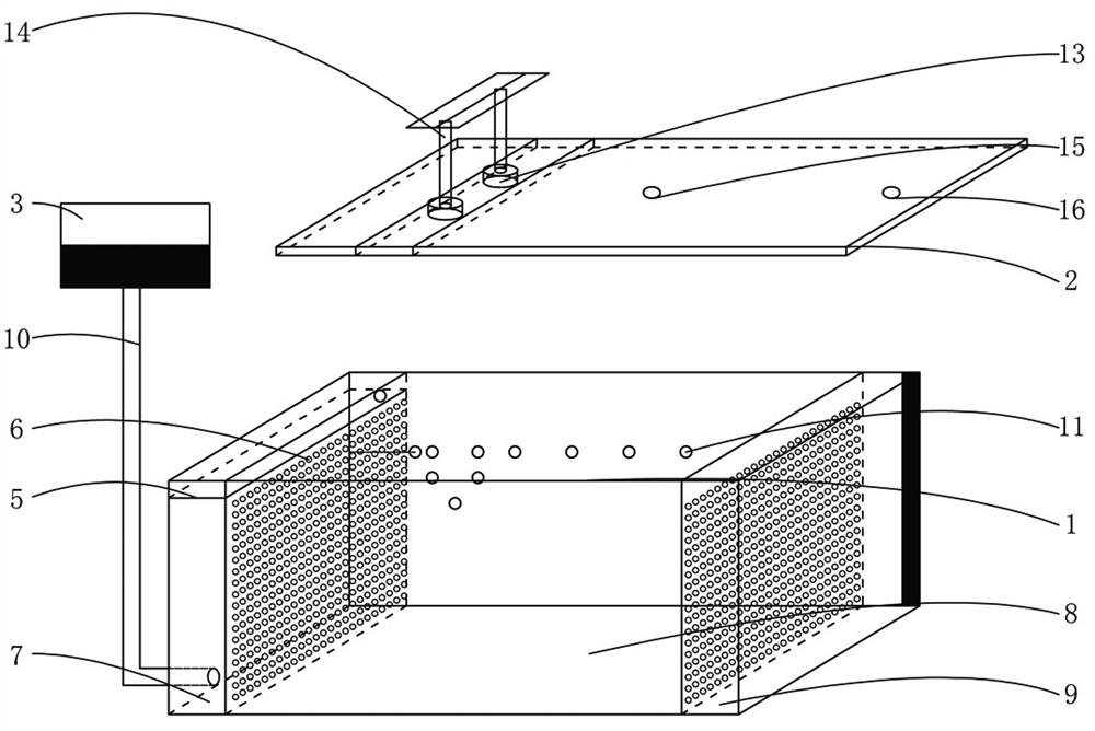
[0026] Embodiment 1: This embodiment aims to provide a seepage deformation device for embankment foundation under vertical load, which is mainly used in the study of the seepage capacity of embankment foundation, so as to simulate the pressure of seepage water in the embankment foundation under vertical load In order to ensure the safety of the embankment project, in this embodiment, a model groove 1 and a plastic anti-seepage composite vertical plate 4 are provided mainly for the seepage deformation device of the embankment foundation in this embodiment.

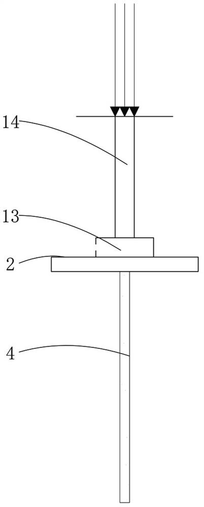
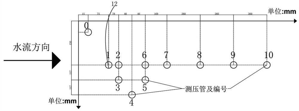
[0027] In a specific structure, such as Figure 1-3As shown in , a device for seepage deformation of embankment foundation under vertical load, including model groove 1, loading plate 2, water head control box 3 and plastic anti-seepage composite vertical plate 4, model groove 1 is surrounded by pressure bearing Plate 5, the inner sides of the pressure plates 5 on both sides are provided with sand separators 6. The sand sep...

Embodiment 2

[0029] Embodiment 2: This embodiment is basically the same as Embodiment 1, and the difference lies in the further description of the specific structure of the water head control box 3 in this embodiment.

[0030] In a specific structure, such as figure 1 As shown in the figure, the water head control box 3 guides the water into the pressure-bearing area 7 through the water pipe 10 to simulate the water near the embankment foundation; the two sand separators 6 are respectively arranged at a distance of 50 centimeters from the pressure-bearing plates on both sides, close to the water head. The pressure-bearing area 7 on the side 3 of the control box is used to simulate the water level, and it is far away from the flat water area 9 on the side of the head control box 3 for water storage.

Embodiment 3

[0031] Embodiment 3: This embodiment is basically the same as Embodiment 1, and the difference lies in the further description of the specific structure of the loading board 2 in this embodiment.

[0032] In a specific structure, such as Figure 3-6 As shown in , the loading plate 2 is provided with four guide cylinders 17 distributed in a rectangular shape, and a connecting rod 18 is inserted into the guide cylinder 17. The lower end of the heavy object is fixed with a flat plate 19; the plastic anti-seepage composite vertical plate 4 simulates the anti-seepage structure in the embankment foundation, which can only simulate vertical infiltration, and the embankment foundation also has lateral infiltration, which will also affect the research structure. The structure of the lateral permeability of the sand in the groove area 8 is not comprehensive enough. The guide cylinder 17, the connecting rod 18 and the flat plate 19 are set together. When in use, the flat plate 19 is plac...


PUM


Abstract

The invention belongs to the technical field of embankment engineering and flood control and fighting, and particularly relates to an embankment foundation seepage deformation device under the action of vertical load, which comprises a model tank, a loading plate, a water head control box and a plastic seepage-proofing composite vertical plate, deformation of the model tank under the condition of overhigh water pressure can be effectively prevented; during loading, the two guide column bases on the loading plate are matched with the supporting columns to transmit loads, so that the loads are more uniformly loaded to the embankment foundation, and the situation that a soil body deforms due to the fact that the load at a certain position is too large is prevented; the model groove is divided into three areas by the sand partition plates, the pressure bearing area enables water pressure to uniformly act on the embankment foundation, the sand groove area is used for placing an embankment foundation model, the water leveling area is used for collecting seepage water discharged by the embankment foundation, the sand partition plates enable an embankment foundation material not to penetrate into other areas, and the plastic anti-seepage composite vertical plates simulate an anti-seepage structure in the embankment foundation. Through the setting, the test is closer to the real situation, and the obtained data is more real and effective.

Description

technical field [0001] The invention belongs to the technical fields of embankment engineering and flood control and flood resistance, and in particular relates to a seepage deformation device for embankment foundations under the action of vertical loads. Background technique [0002] my country has a vast territory and has a large number of rivers and lakes. Due to the complex and diverse natural and geographical factors, there have always been a large number of flood disasters, which have brought serious threats to the lives and properties of the people and are not conducive to social and economic development. Since liberation, after years of hard work and governance, my country has initially completed seven major river flood control projects, including the Yangtze River and the Yellow River, which has guaranteed social stability to a certain extent. According to the long-term flood control practice, the length of the dykes currently built in my country is 430,000 km. Due...

Claims


Application Information

Patent Timeline
Patent Type & Authority Applications(China)
IPC IPC(8): G01N3/14G01N15/08
CPCG01N3/14G01N15/0826G01N2203/0003G01N2203/0019G01N2203/0033Y02A10/11
Inventor 柴启辉冯凌云李乾徐良杰王祥宇万芳丁泽霖
Owner NORTH CHINA UNIV OF WATER RESOURCES & ELECTRIC POWER
Learn More