
COB lamp strip manufacturing method and COB lamp strip

A manufacturing method and technology of light strips, which are applied to semiconductor devices of light-emitting elements, lighting and heating equipment, electric solid-state devices, etc., can solve problems such as inconsistent thickness and uneven light emission of COB light strips, and achieve the effect of ensuring uniformity

Pending Publication Date: 2022-08-05
SHENZHEN COOLIGHT OPT ELE CO LTD
View PDF0 Cites 0 Cited by
  • Summary
  • Abstract
  • Description
  • Claims
  • Application Information

AI Technical Summary

Problems solved by technology

However, the existing COB light strips usually use the glue-dropping method to coat the phosphor powder on the LED chip. During the glue-dropping process, due to the fluidity of the glue, different places will appear when the glue is solidified on the circuit board. The problem of inconsistent thickness will affect the problem of uneven light emission of COB light strips

Method used


Image

  • COB lamp strip manufacturing method and COB lamp strip
  • COB lamp strip manufacturing method and COB lamp strip
  • COB lamp strip manufacturing method and COB lamp strip

Examples


Embodiment 1

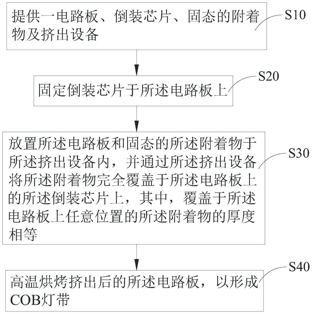
[0044] see figure 1 , Embodiment 1 of the present application provides a method for manufacturing a COB light strip 100, comprising the following steps:

[0045] S10: Provide a circuit board 10, a light-emitting chip 20, a solid attachment 30 and an extrusion device.

[0046] S20 : ​​Fixing the light-emitting chip 20 on the circuit board 10 .

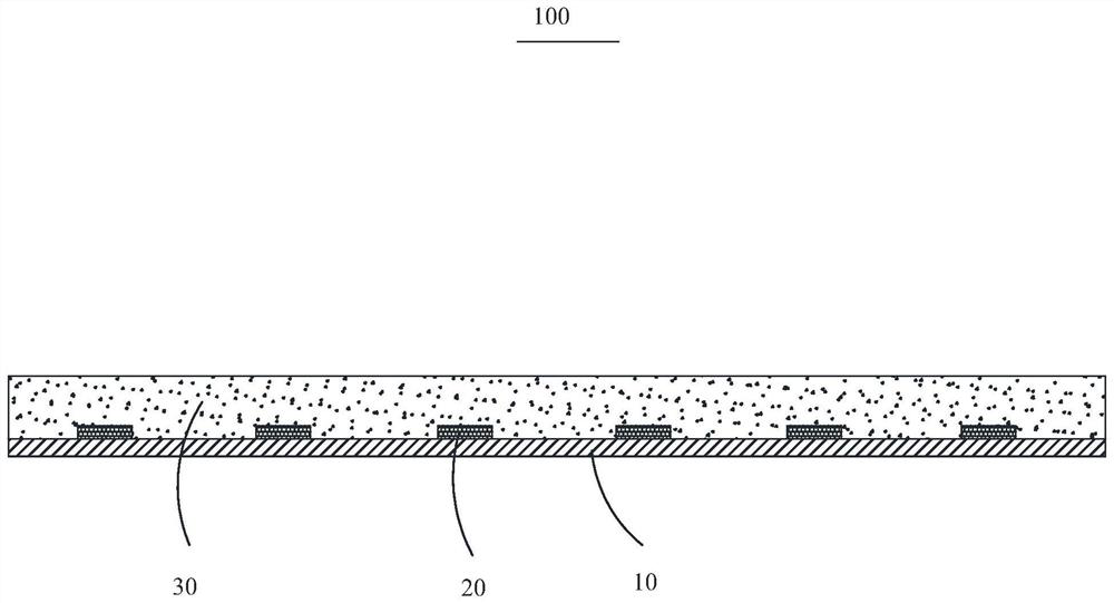
[0047] S30: Place the circuit board 10 and the solid attachment 30 in the extrusion equipment, and completely cover the light-emitting light on the circuit board 10 with the attachment 30 through the extrusion equipment On the chip 20 , the thickness of the attachment 30 covering any position on the circuit board 10 is equal.

[0048] S40 : baking the extruded circuit board 10 at a high temperature to form a COB light strip 100 .

[0049] In one embodiment, the light-emitting chip 20 is an LED chip, which is fixed to the circuit board 10 and is electrically connected to the circuit board 10 to be turned on or off under the control of...

Embodiment 2

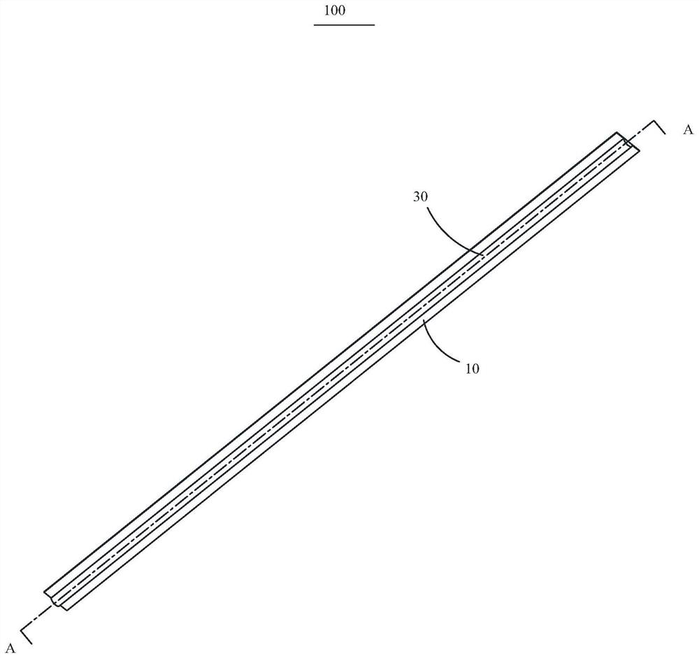
[0080] The second embodiment of the present application provides a COB light strip 100 , which includes a circuit board 10 , a light-emitting chip 20 and an attachment 30 . The light-emitting chip 20 is fixed on the circuit board 10 , and the attachment 30 is attached to the circuit board 10 and completely covers the light-emitting chip 20 .

[0081] It should be noted that the COB light strip 100 in the second embodiment is made by the preparation method of the COB light strip 100 in the first embodiment. Therefore, there is a COB light strip in the preparation method of the COB light strip 100 involved in the first embodiment. All the beneficial effects of 100 will not be repeated here.

[0082] Preferably, the circuit board 10 is a double-layer flexible circuit board 10 .

[0083] Further, the light-emitting chip 20 includes a plurality of lamp beads disposed on the circuit board 10 and electrically connected to the circuit board 10 . Preferably, the plurality of lamp bead...


PUM

PropertyMeasurementUnit
lengthaaaaaaaaaa

Abstract

The invention provides a manufacturing method of a COB lamp strip. The manufacturing method comprises the following steps that a circuit board, a light-emitting chip, a solid attachment and extrusion equipment are provided; fixing a light-emitting chip on the circuit board; the circuit board and the solid attachments are placed in the extrusion equipment, the light-emitting chip on the circuit board is completely covered with the attachments through the extrusion equipment, and the thicknesses of the attachments covering any position on the circuit board are equal; and baking the extruded circuit board at a high temperature to form the COB lamp strip. The invention further provides a COB lamp strip. According to the manufacturing method of the COB lamp strip and the COB lamp strip, the light-emitting chip is fixed to the circuit board, the solid attachments are extruded to the circuit board through the extrusion equipment, and the thicknesses of the attachments extruded to any position of the circuit board are made to be equal, so that it is guaranteed that light transmitting and light emitting of the COB lamp strip are consistent at all positions; therefore, the light emitting uniformity of the COB lamp strip is ensured.

Description

【Technical field】 [0001] The present application relates to the technical field of lamps, and in particular, to a method for manufacturing a COB lamp strip and a COB lamp strip. 【Background technique】 [0002] COB light strip is a strip-shaped LED product formed by welding and assembling LED chips on FPC (F1 exible Printed Circuit, flexible circuit board) and coating the surface of LED chips with continuous silica gel. It has long service life, energy saving and environmental protection. Therefore, it has been more and more widely used in the field of lighting. However, the existing COB light strips usually use the glue drop method to coat the phosphor on the LED chip. During the glue drop process, due to the fluidity of the glue, the glue will appear in different places when it solidifies on the circuit board. The problem of inconsistent thickness will affect the problem of uneven light emission of COB light strips. [Content of the invention] [0003] In view of this, i...

Claims


Application Information

Patent Timeline
Patent Type & Authority Applications(China)
IPC IPC(8): H01L33/50H01L25/075F21S4/24F21K9/90F21Y115/10
CPCH01L33/505H01L25/0753F21S4/24F21K9/90F21Y2115/10H01L2933/0041
Inventor 易凯许学勤
Owner SHENZHEN COOLIGHT OPT ELE CO LTD
Learn More