
Solar photovoltaic panel assembly

A solar photovoltaic panel and photovoltaic panel technology, applied in the field of solar photovoltaic panel components, can solve problems such as rainwater penetration, solar panel scratches, splicing surface impact, etc., and achieve the effect of preventing rainwater impact, avoiding scattered wires, and avoiding rainwater penetration

Pending Publication Date: 2022-08-05
徐州日托光伏科技有限公司
View PDF0 Cites 3 Cited by
  • Summary
  • Abstract
  • Description
  • Claims
  • Application Information

AI Technical Summary

Problems solved by technology

[0002] With the development of economy and social progress, solar cells gradually enter family life. The most important part of solar cells is solar photovoltaic modules. Solar photovoltaic modules used in households are generally installed on high places such as roofs or balcony external platforms. It is very inconvenient to adjust components such as angles, etc.; there are still some shortcomings: solar panels are installed in series on the protective backplane by multiple cells closely arranged in series, and the overall fixed structure is installed by the frame. It is facing upward to receive sunlight, rain and snow weather, there will be problems of rainwater penetration, and even bad weather will have a serious impact on the splicing surface, resulting in damage to solar photovoltaic modules. In addition, solar panels may be scratched during transportation. marks or cracks, resulting in defective solar photovoltaic modules and affecting the use; the installation angle of solar photovoltaic modules used in households is often fixed, which cannot meet the needs of each customer for the installation angle of solar photovoltaic modules

Method used


Image

  • Solar photovoltaic panel assembly
  • Solar photovoltaic panel assembly
  • Solar photovoltaic panel assembly

Examples


Embodiment Construction

[0035] The technical solutions in the implementation of the present invention will be clearly and completely described below with reference to the accompanying drawings. The described embodiments are only a part of the embodiments of the present invention, rather than all the embodiments. Based on the embodiments of the present invention, all other embodiments obtained by those of ordinary skill in the art without creative work fall within the protection scope of the present invention.

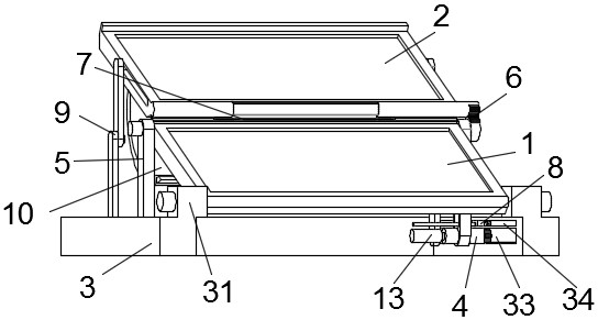
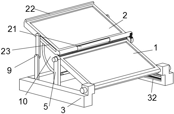
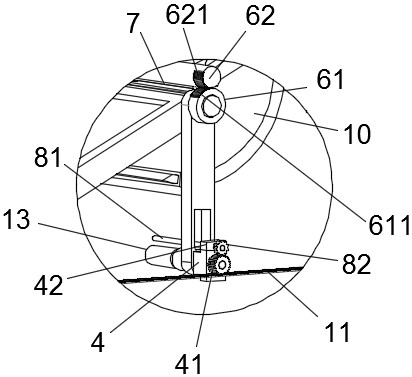
[0036] like Figure 1 to Figure 10As shown, a solar photovoltaic panel assembly is provided, the first embodiment of the present invention includes a U-shaped base composed of two parallel vertical base plates 3 and a horizontal base plate connected to one end of the two longitudinal base plates. The U-shaped base The purpose is to be used for the installation of solar photovoltaic modules, as well as to adjust the state of solar photovoltaic modules when they are in use or to adjust the state...


PUM

PropertyMeasurementUnit
angleaaaaaaaaaa

Abstract

The invention discloses a solar photovoltaic panel assembly, which belongs to the technical field of photovoltaic equipment and comprises longitudinal bottom plates arranged in parallel, horizontal T-shaped grooves are formed in opposite side surfaces of the longitudinal bottom plates, a first photovoltaic panel is rotationally connected with a connecting support lug and an adjusting plate, the connecting support lug is arranged at one end of each longitudinal bottom plate, and the adjusting plate is arranged on a guide sliding block. The guide sliding blocks are connected with the horizontal T-shaped grooves in a sliding and clamping mode, one guide sliding block is provided with a driving mechanism, the adjusting plate arranged on the same side of the driving mechanism is connected with a linkage piece, a connecting hinge is arranged between the second photovoltaic plate and the first photovoltaic plate, and the second photovoltaic plate is further connected with a supporting and folding plate. And the linkage piece rotates along with the rotation of the adjusting plate and drives the second photovoltaic panel piece to rotate. According to the invention, a split type structure is adopted, the solar photovoltaic panel assembly can be self-protected in rainy and snowy severe weather, and damage is reduced; and meanwhile, the requirements of customers on the use angle of the solar photovoltaic module are met.

Description

technical field [0001] The invention relates to a solar photovoltaic panel assembly, which belongs to the technical field of photovoltaic equipment. Background technique [0002] With the development of economy and the progress of society, solar cells have gradually entered family life. The most important part of solar cells is solar photovoltaic modules. The adjustment of components such as angles is very inconvenient; there are still some deficiencies: the solar panels are closely arranged in series on the protective backplane, and the overall fixed structure is installed by the frame. It is upward to receive sunlight. In rainy and snowy weather, there will be a problem of rainwater penetration, and even in bad weather, it will have a serious impact on the splicing surface, resulting in damage to the solar photovoltaic modules. In addition, the solar panels will be scratched during transportation. marks or cracks, resulting in defective solar photovoltaic modules and affe...

Claims


Application Information

Patent Timeline
Patent Type & Authority Applications(China)
IPC IPC(8): H02S20/30H02S40/34H02S40/10F24S30/425B65H75/44
CPCH02S20/30H02S40/34H02S40/10F24S30/425B65H75/44Y02B10/10Y02E10/50
Inventor 张凤鸣陈晓辉
Owner 徐州日托光伏科技有限公司
Learn More