Flap traction device for breast surgery
A pulling device and a technique for surgery, applied in the directions of surgery, operating table, stereotaxic surgical instruments, etc., can solve the problems of fixed position, inability to better meet the pulling requirements of breast skin flaps, and inability to clamp the skin flaps, etc. Easy-to-place effects
- Summary
- Abstract
- Description
- Claims
- Application Information
AI Technical Summary
Problems solved by technology
Method used
Image

Examples
Embodiment 1
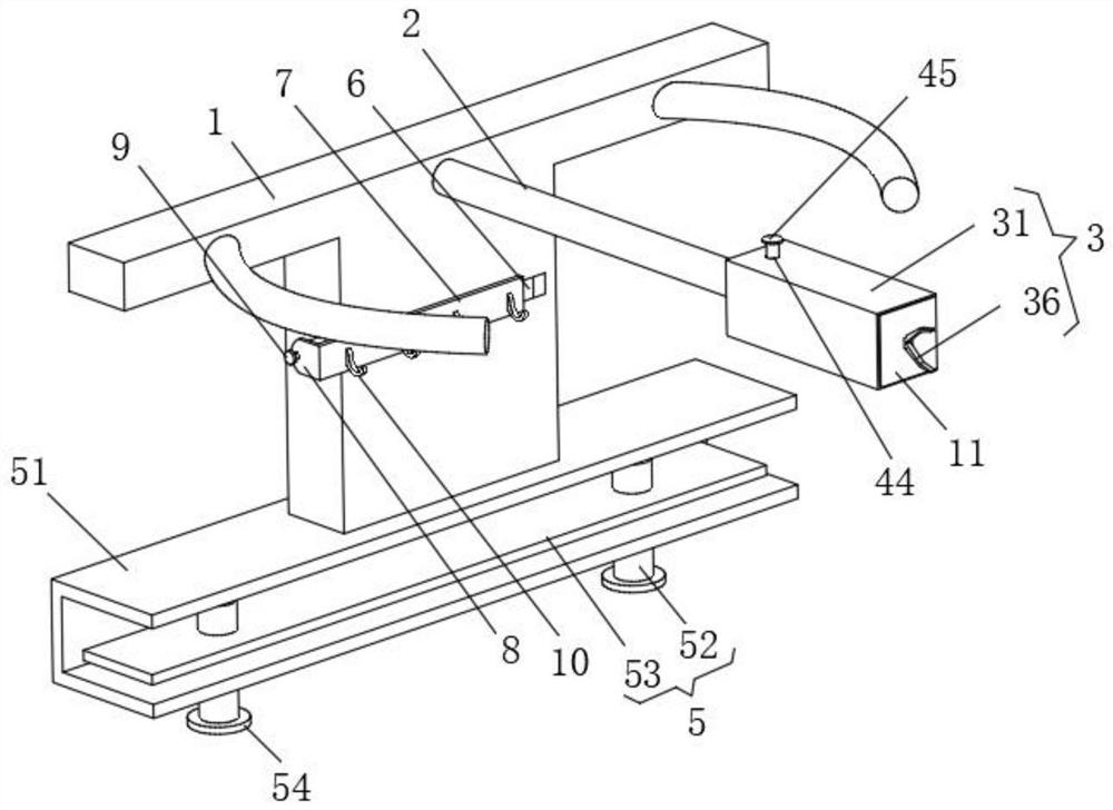
[0027] Embodiment 1: a breast surgery skin flap pulling device, comprising a T-shaped brace 1, a clamping unit 3 and a clamping power unit 4;
[0028] The right end of the upper side of the T-shaped support plate 1: is connected to the left end of the universal arm 2;
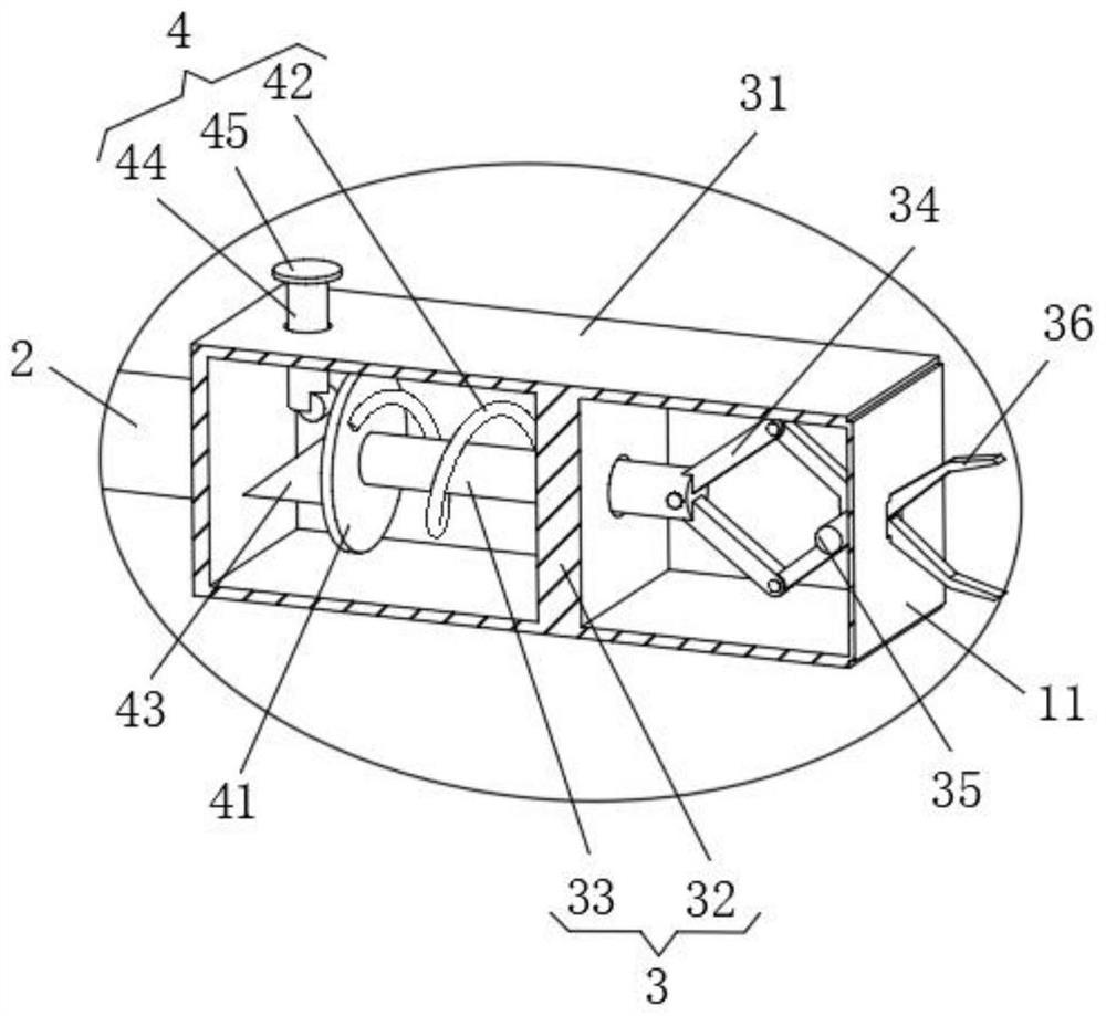
[0029] Clamping unit 3: includes a clamping box 31, a middle hole plate 32, a sliding cross column 33, a short pulling rod 34, a clamping hand shaft 35 and a clamping rod 36, the right end of the universal arm 2 is connected to the left end of the clamping box 31, and the clamp A middle hole plate 32 is installed in the middle of the inside of the tight box 31, the sliding cross column 33 is slidably connected to the center of the middle hole plate 32, and the left ends of the two pulling short rods 34 are movably connected to the right end of the sliding cross column 33 through the short rod rotating shaft, The inner right end of the clamping box 31 is provided with a clamping hand shaft 35, the middle parts o...
Embodiment 2
[0033] The difference between this embodiment and the first embodiment is that:
[0034] In this embodiment, a fixing unit 5 is also included. The fixing unit 5 includes a fixing frame 51 , a fixing screw 52 , a fixing long plate 53 and a rotating rod plate 54 . The lower end of the T-shaped support plate 1 is connected to the upper end of the fixing frame 51 . The fixing frame The lower end of 51 is threadedly connected with two fixing screws 52, the upper ends of the two fixing screws 52 are respectively connected with the front and rear ends of the fixed long plate 53 in rotation, and the lower ends of the two fixing screws 52 are installed with rotating rod discs 54. By rotating the rotary lever plate 54, the fixed long board 53 can be clamped to the clamped bed board by the two fixing screws 52, so that the device can be fixed.
[0035] It also includes a chute 6 and a clamping plate 7 . The middle of the right end of the T-shaped support plate 1 is provided with a chute ...
Embodiment 3
[0038] The difference between this embodiment and the first embodiment is that:
[0039] In this embodiment, a clamping fixing bolt 9 is also included, and the left end of the arc-shaped fixing plate 8 is threadedly connected to the front end of the T-shaped support plate 1 through the clamping fixing bolt 9 . By clamping the fixing bolts 9, the arc-shaped fixing plate 8 can be well connected with the T-shaped support plate 1 to realize fixing.
[0040] A hook 10 is also included, and the hook 10 is installed on the right end of the snap plate 7 . With the hook 10, the placement of tools during surgery is more convenient.
[0041] It also includes a sealing soft board 11 , and the right end of the clamping box 31 is installed with the sealing soft board 11 . Through the deformation of the sealing soft plate 11 , the clamping box 31 can be well sealed without affecting the work of the two clamping rods 36 .
[0042] When in use: firstly, by rotating the rotary lever plate 54, ...
PUM
 Abstract
Description
Claims
Application Information
 - R&D
- Intellectual Property
- Life Sciences
- Materials
- Tech Scout
- Unparalleled Data Quality
- Higher Quality Content
- 60% Fewer Hallucinations
Browse by: Latest US Patents, China's latest patents, Technical Efficacy Thesaurus, Application Domain, Technology Topic, Popular Technical Reports.
© 2025 PatSnap. All rights reserved.Legal|Privacy policy|Modern Slavery Act Transparency Statement|Sitemap|About US| Contact US: help@patsnap.com