
Composite material textile fabric manufacturing equipment

A technology for manufacturing equipment and composite materials, which is applied to auxiliary equipment for weaving, textiles, papermaking, textiles, etc. It can solve the problems of difficulty in maintaining rapier looms, affecting the service life of the pull belt, and the wear and tear of the pull belt, etc., to achieve convenience Replacement and maintenance, convenient disassembly and assembly, and the effect of reducing tension

Pending Publication Date: 2022-08-09
ANHUI HENGYI TEXTILE TECH CO LTD
View PDF9 Cites 0 Cited by
  • Summary
  • Abstract
  • Description
  • Claims
  • Application Information

AI Technical Summary

Problems solved by technology

[0002] In actual production, rapier looms are usually used to produce composite textile fabrics. Although the existing rapier looms can weave composite textile fabrics, there are certain defects in the process of use, such as Figure 8 As shown, for example, the flying shuttle and the pulling belt of the existing rapier loom move back and forth on the half-wrapped jaw-shaped guide rail plate. The guide rail wears the pulling belt greatly, which affects the service life of the pulling belt and needs to be replaced frequently Maintenance; for example, when the existing rapier loom is ready for weaving, additional components need to be installed to adjust the tension of the warp yarn group bound on the cloth roll, and the operation is cumbersome; for example, the existing rapier loom During the weaving work, lint will be produced, and the lint is easy to attach to the various shafts and transmission parts of the rapier loom, making it difficult to maintain the rapier loom in the later stage

Method used


Image

  • Composite material textile fabric manufacturing equipment
  • Composite material textile fabric manufacturing equipment
  • Composite material textile fabric manufacturing equipment

Examples


Embodiment Construction

[0026] In order to further illustrate the technical means and effects adopted by the present invention to achieve the predetermined purpose of the invention, the specific embodiments, structures, features and effects of the present invention are described in detail below in conjunction with the accompanying drawings and preferred embodiments.

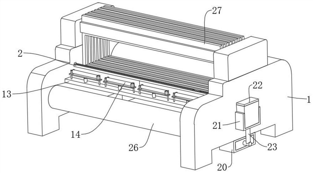
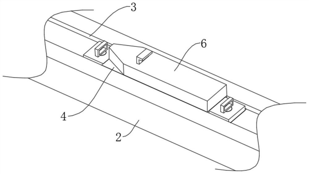
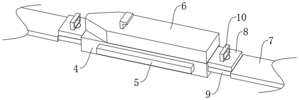
[0027] refer to Figure 1-Figure 7 , a composite material textile cloth manufacturing equipment, comprising a rapier loom body 1, on the inner side wall of the rapier loom body 1 and close to the side position rotation is provided with a let-off roller, the let-off roller is wound with a sizing finish The warp yarns, the inner side wall of the rapier loom body 1 and the side away from the let-off roller are rotated and provided with a cloth winding roller 26, and between the inner side walls of the rapier loom body 1 and near the middle position are movably provided with multiple Warp yarn frames 27, each warp yarn frame 27 is movably p...


PUM


Abstract

The invention discloses composite textile fabric manufacturing equipment which comprises a rapier loom body, a guide rail plate is fixed to the inner side wall of the rapier loom body, a guide rail sliding groove is formed in the upper end face of the guide rail plate, a movable sliding block is slidably connected into the guide rail sliding groove, and two limiting sliding grooves are symmetrically formed in the inner side wall of the guide rail sliding groove; limiting sliding blocks used in cooperation with the limiting sliding grooves are fixed to the two sides of the movable sliding block, a flying shuttle is fixed to the upper end face of the movable sliding block, and pulling belts are arranged on the two sides of the movable sliding block. Through cooperation of the guide rail plate and the guide rail sliding groove, the movable sliding block and the pulling belt can move in the guide rail sliding groove, friction of the side wall of the guide rail plate to the pulling belt is reduced, and therefore abrasion to the pulling belt is reduced, and the damage rate of the pulling belt is reduced.

Description

technical field [0001] The invention relates to the technical field of textile equipment, in particular to a composite material textile cloth manufacturing equipment. Background technique [0002] In actual production, rapier looms are usually used to produce composite textile fabrics. Although the existing rapier looms can weave composite textile fabrics, there are certain defects in the process of use, such as Figure 8 As shown, for example, the shuttle and the pulling belt of the existing rapier loom move back and forth on the semi-wrapped gripper-shaped guide rail plate. Maintenance; for example, when the existing rapier loom is ready for weaving, additional components need to be installed to adjust the tension of the warp yarn group tied to the cloth roll, which is cumbersome to operate; for example, the existing rapier loom During the weaving work, fluff will be produced, and the fluff will easily adhere to the various shafts and transmission parts of the rapier loom,...

Claims


Application Information

Patent Timeline
Patent Type & Authority Applications(China)
IPC IPC(8): D03D47/18D03D49/04D03D49/20D03J1/00
CPCD03D47/18D03D49/04D03D49/20D03J1/002
Inventor 李贺宋明起
Owner ANHUI HENGYI TEXTILE TECH CO LTD
Learn More