
Anti-collision type wind power blade

A technology of wind blades and anti-collision, which is applied in the direction of wind power generators, wind power generators, wind power generation, etc. in the same direction as the wind, and can solve problems such as easy collision deformation of inserted round rods, easy impact damage of blades, and damage to internal parts of birds, etc. , to achieve the effect of being easy to promote and use, preventing birds from entering, and eliminating dangers

Pending Publication Date: 2022-08-09
南京芳兴晓科技有限公司
View PDF0 Cites 0 Cited by
  • Summary
  • Abstract
  • Description
  • Claims
  • Application Information

AI Technical Summary

Problems solved by technology

[0003] The purpose of the present invention is to provide an anti-collision wind blade to solve the problem that the outer side of the blade is thin and easily damaged by impact when the existing wind blade proposed in the above background technology is in use, which affects normal use, increases maintenance costs, and protects There is space in the middle of the outside world, and birds are easy to nest for a long time, causing damage to internal parts, reducing protection, and increasing danger. Moreover, the transportation of blades makes the plug-in round rods easy to collide and deform, which affects normal installation and reduces practicability. The connection port will be misplaced, and it needs to be re-drilled, which increases the difficulty of use and does not meet the needs of modern people.

Method used


Image

  • Anti-collision type wind power blade
  • Anti-collision type wind power blade
  • Anti-collision type wind power blade

Examples


Embodiment Construction

[0033] The technical solutions in the embodiments of the present invention will be clearly and completely described below with reference to the accompanying drawings in the embodiments of the present invention. Obviously, the described embodiments are only a part of the embodiments of the present invention, but not all of the embodiments. Based on the embodiments of the present invention, all other embodiments obtained by those of ordinary skill in the art without creative efforts shall fall within the protection scope of the present invention.

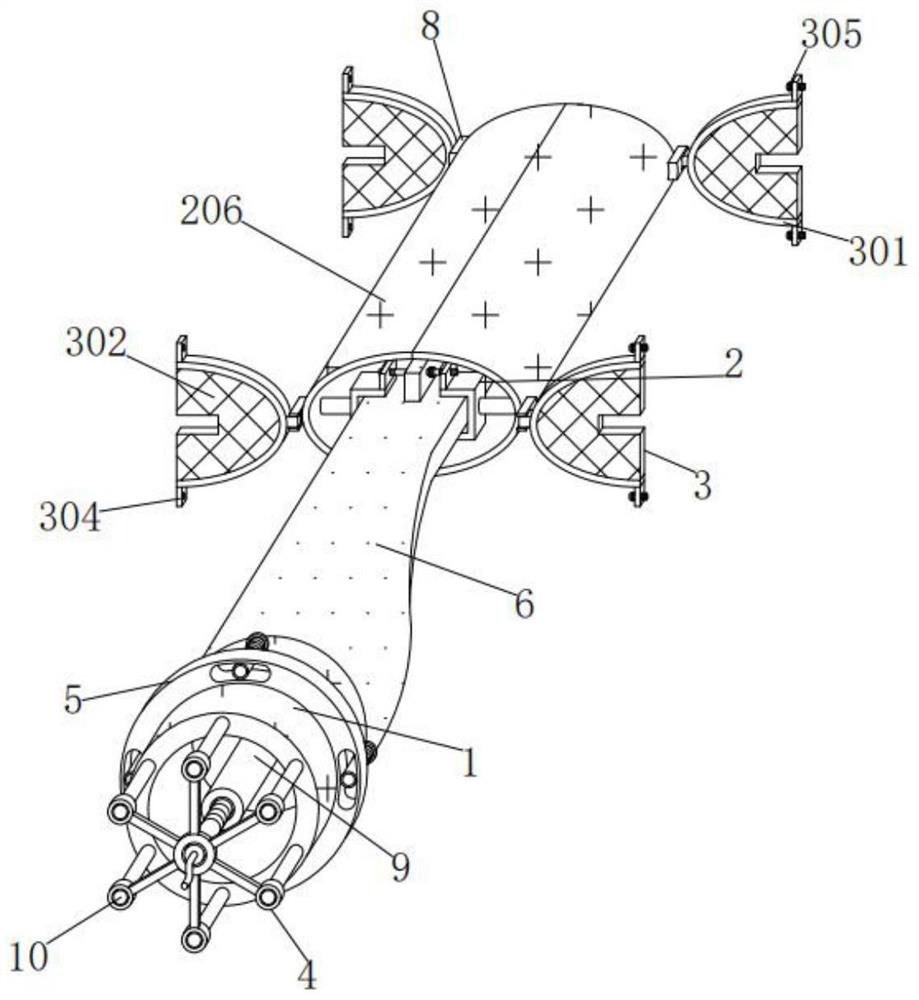
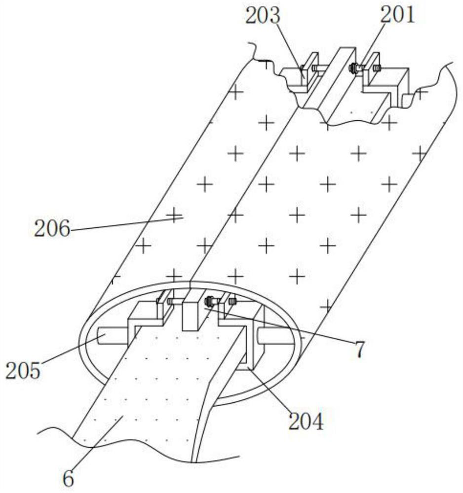
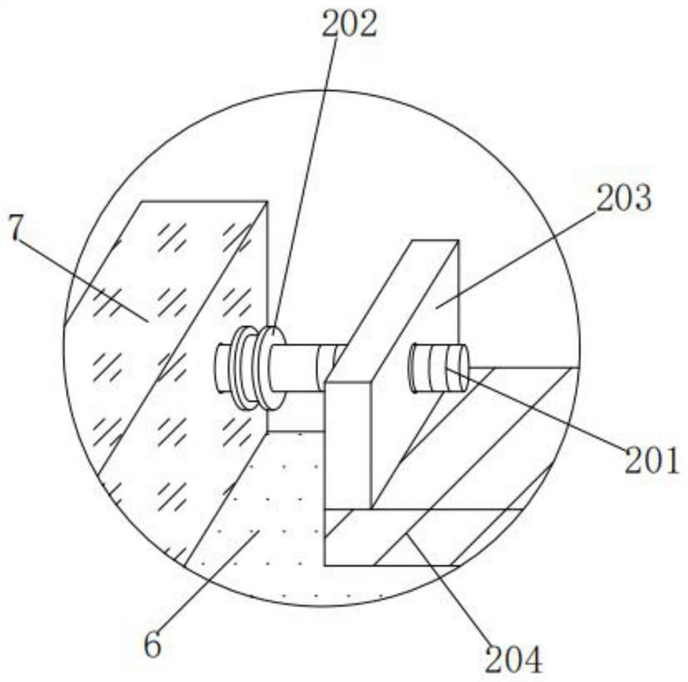
[0034] see Figure 1-6 , The present invention provides a technical solution: an anti-collision wind blade, comprising a cylinder 1, a blade 6 is fixed on the rear end surface of the cylinder 1, the upper and lower sides of the blade 6 are respectively fitted with a straight plate 7, The outer side is respectively connected with a protective structure 2. The protective structure 2 includes a stud 201, a turning plate 202, a square pla...


PUM


Abstract

The anti-collision type wind power blade comprises a cylinder, a blade body is fixedly connected to the rear end face of the cylinder, straight plates are attached to the upper side and the lower side of the blade body respectively, the outer sides of the straight plates are connected with protection structures respectively, and each protection structure comprises a double-end stud, a rotating plate, a square plate, a support, a transverse rod and a shell. The outer wall of the double-end stud is rotationally connected with a notch in the outer wall of the straight plate, and the right side of the outer wall of the double-end stud is connected with the inner wall of the rotating plate in a welded mode. According to the anti-collision type wind power blade, the transverse rod drives the shell to be combined, the shell plays an anti-collision protection role, collision damage is prevented, normal use is ensured, the maintenance cost is reduced, damage to internal parts is avoided, the protection performance is ensured, danger is eliminated, supporting of the round rod is achieved, deformation caused by collision during transportation is prevented, normal installation is ensured, and practicability is improved; and the problem of connection conflict is solved, re-punching is not needed, the use difficulty is reduced, and popularization and use are facilitated.

Description

technical field [0001] The invention relates to the technical field of anti-collision type wind blades, in particular to an anti-collision type wind blade. Background technique [0002] The wind turbine blade is one of the core components of the wind turbine. The quality of its design will be directly related to the performance and benefit of the wind turbine. When the existing wind blade is in use, the outer side of the blade is thin and easily damaged by impact, which affects normal use. Increase maintenance costs and protect the space in the middle of the outside world. Birds are easy to nest and cause damage to internal parts for a long time, reducing protection and increasing danger. Moreover, the transportation of blades makes the plug-in round rod easy to collide and deform, which affects normal installation and reduces the risk of damage. Practical, at the same time, the blade installation will cause the connection port to be dislocated, and it needs to be re-drilled...

Claims


Application Information

Patent Timeline
Patent Type & Authority Applications(China)
IPC IPC(8): F03D1/06
CPCF03D1/0675Y02E10/72
Inventor 骆晓芳
Owner 南京芳兴晓科技有限公司
Learn More