Check patentability & draft patents in minutes with Patsnap Eureka AI!

Decoding method for absolute photoelectric angle sensor

An angle sensor, absolute technology, applied in the direction of converting sensor output, instruments, optical devices, etc., can solve the problems of complex integration of coarse code and fine code, low reliability, long debugging time, etc., to simplify the signal processing circuit, high Reliability and repeatability, the effect of speeding up calculations

Pending Publication Date: 2022-08-09
大连探索者科技有限公司
View PDF0 Cites 0 Cited by
  • Summary
  • Abstract
  • Description
  • Claims
  • Application Information

AI Technical Summary

Problems solved by technology

[0003] The existing absolute photoelectric angle sensor is an optical, mechanical and electrical integration and digital product. It adopts gray code and matrix code mixed coding technology, which has the characteristics of high precision and wide measurement range. However, its coding method requires multiple code tracks and multiple groups Optocouplers generally require more than ten barcode lines, and the radial width of the grating is relatively large, resulting in a larger volume of the photoelectric angle sensor, high device cost, long debugging time, and low reliability
The decoding process of the existing absolute photoelectric angle sensor requires a lot of signal processing, and the calculation is cumbersome. The rough code and fine code integration technology of determining the approximate position and the fine code to determine the specific position are often used, which requires more hardware resources such as electronic components. , leading to a large cumulative calculation error in the decoding process, complex integration of coarse code and fine code, resulting in long operation time and slow response speed of the absolute photoelectric angle sensor, resulting in the inability of the absolute photoelectric angle sensor to have higher accuracy and reliability sex

Method used


Image

  • Decoding method for absolute photoelectric angle sensor
  • Decoding method for absolute photoelectric angle sensor
  • Decoding method for absolute photoelectric angle sensor

Examples


Embodiment Construction

[0088] In order to make the technical problems solved by the present invention, the technical solutions adopted and the technical effects achieved more clearly, the present invention will be further described in detail below with reference to the accompanying drawings and embodiments. It should be understood that the specific embodiments described herein are only used to explain the present invention, but not to limit the present invention. In addition, it should be noted that, for the convenience of description, the drawings only show some but not all of the contents related to the present invention.

[0089] Embodiments of the present invention provide a decoding method for an absolute photoelectric angle sensor.

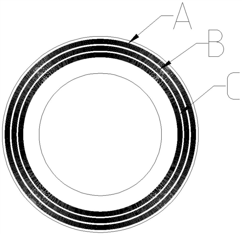
[0090] like figure 1 As shown in the figure, the absolute photoelectric angle sensor has an encoder disk; the encoder disk has three code channels, namely A code channel, B code channel and C code channel; The total number of scribe lines are NA, NB and NC respe...


PUM


Abstract

The invention relates to the technical field of photoelectric measurement, and provides an absolute photoelectric angle sensor decoding method, which comprises the following steps: step 100, calculating an A code channel periodic angle value EA; step 200, calculating an angle value EB of a B code channel period according to the method in the step 100; step 300, calculating an angle value EC of a C code channel period according to the method in the step 100; step 400, according to the A code channel period angle value EA and the B code channel period angle value EB, calculating an AB code channel temporary angle ABJ; step 500, calculating a temporary angle BCJ of the BC code channel according to the angle value EB of the B code channel period and the angle value EC of the C code channel period; and step 600, calculating an angle Angle corresponding to the current position of the absolute photoelectric angle sensor. The precision, the operation speed and the reliability of the absolute photoelectric angle sensor can be improved.

Description

technical field [0001] The invention relates to the technical field of photoelectric measurement, in particular to a decoding method for an absolute photoelectric angle sensor. Background technique [0002] Absolute photoelectric angle sensor is an integrated and digital product of light, machine and electricity. It is mainly used for precise measurement of shaft angle. It has the advantages of high precision, wide measurement range, small size, light weight and good reliability. Using the technology of this patent can make the product have higher measurement accuracy, higher reliability and repeatability, which not only simplifies the signal processing circuit of the encoder, improves the accuracy and reliability of the encoder, but also realizes the encoder The miniaturization of the application, saving space, and the volume is smaller than the absolute angle sensor of the same precision. [0003] The existing absolute photoelectric angle sensor is an integrated and digit...

Claims


Application Information

Patent Timeline
IPC IPC(8): G01D5/347G01B11/26
CPCG01D5/347G01B11/26
Inventor 廖祖平张大权王国富衣洪梅
Owner 大连探索者科技有限公司
Features
  • R&D
  • Intellectual Property
  • Life Sciences
  • Materials
  • Tech Scout
  • Unparalleled Data Quality
  • Higher Quality Content
  • 60% Fewer Hallucinations
Learn More