Mounting structure for magnetic head

A mounting structure and magnetic head technology, which is applied in the configuration/installation, fixed installation, magnetic recording, etc. of the recording head, which can solve the problems of increased number of parts, increased cost, troublesome thread cutting, etc.

Inactive Publication Date: 2004-05-19
ALPS ALPINE CO LTD
View PDF0 Cites 0 Cited by
  • Summary
  • Abstract
  • Description
  • Claims
  • Application Information

AI Technical Summary

Problems solved by technology

[0007] But, in existing magnetic head installation structure, when fixing with screw, must have the collar member 13 that cuts out female thread, and the male screw hole 14 that is fixed with it.
In addition, thread cutting itself is troublesome, the number of parts also increases, and the cost increases. At the same time, assembly work is also troublesome, which is a problem.
[0008] In addition, when soldering, the melting of the four protruding portions 15a tends to deviate, and thus, the bonding strength of the magnetic head and the mounting board 15 deviates, which is also a problem.
Furthermore, the electrical and mechanical adjustment of the resistance welding device, and its maintenance management are also troublesome, which is also a disadvantage.
[0009] In addition, in any of the above mounting structures, the positioning (orientation, tilt, movement, core height, etc.) of the magnetic head on the mounting plate 12 or 15 cannot achieve high precision.
Therefore, when the magnetic head is installed on the machine through the mounting plate 12 or 15, it is necessary to adjust the position (posture) of the magnetic head, which is also a problem.

Method used


Image

  • Mounting structure for magnetic head
  • Mounting structure for magnetic head
  • Mounting structure for magnetic head

Examples


Embodiment Construction

[0025] specific implementation

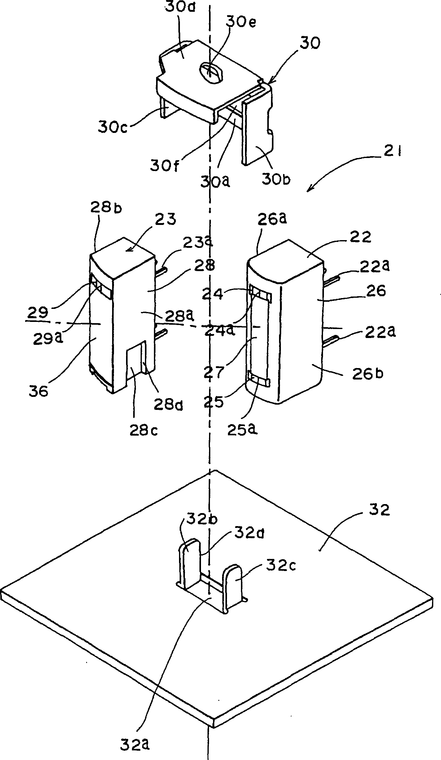
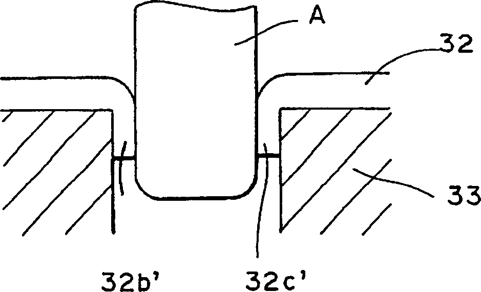
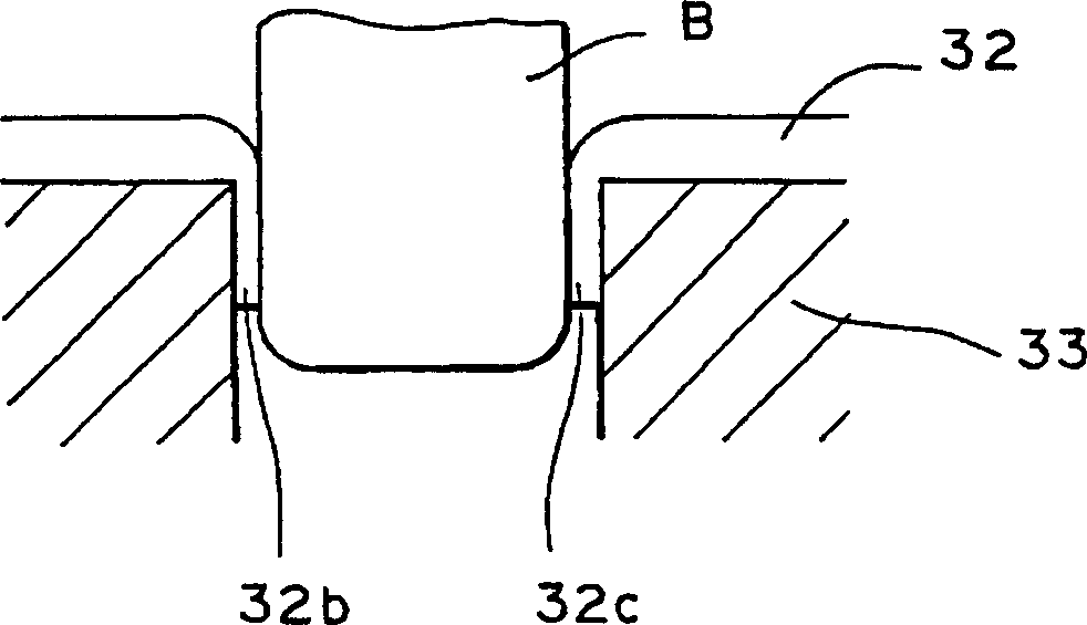
[0026] figure 1 To show an exploded perspective view of the main part of one embodiment of the magnetic head mounting structure of the present invention, by punching holes at given places on the mounting plate 32 made of rolled steel plate or the like, the opening 32a and the opposite sides at its two sides are made. A pair of bent pieces 32b, 32c. Such as Figure 2A , Figure 2B As shown, the forming method of the bent pieces 32b, 32c is to place the mounting plate 32 with a thickness of about 1.2mm on the metal mold 33, as the first process, in Figure 2A In this case, the mounting plate 32 is punched from above with a punch A, and a part thereof is bent to both sides to form bent portions 32b', 32c'. Then, as a second process, in Figure 2B In this process, the above-mentioned bent parts 32b', 32c' are drawn and thinned by using a punch B having a diameter larger than that of the punch A, and the bent parts 32b, 32c are formed to a thi...


PUM


Abstract

The metallic fitting plate 32 is provided with a bent piece 32a, the bent piece 32a is inserted into the join part formed by joining the flank 26a of a 1st magnetic head 22 and the flank 28a of a 2nd magnetic head 23, and an adhesive is charged between the join part and bent piece 32a to fix the 1st and 2nd magnetic heads 22 and 23 to the fitting plate 32.

Description

technical field [0001] The present invention relates to a magnetic head mounting structure, in particular to a magnetic head mounting structure for mounting a magnetic head composed of a composite of a sound / control head and an erasing head for a video cassette recorder (VCR) on a mounting plate. Background technique [0002] Figure 7 It is a front view showing the conventional magnetic head mounting structure of this kind. The magnetic head 1 is composed of a first magnetic head 2 composed of an audio / control head and a second magnetic head 3 composed of an erasing head. The first magnetic head 2 is that the magnetic head core 4 used for sound and the magnetic head core 5 used for control are inserted in the shielding case 6 made of magnetic metals such as permalloy at regular intervals in the magnetic tape width direction; and The gap parts 4a, 5a of each magnetic core 4, 5 are exposed on the magnetic tape sliding contact surface of the shielding cover 6; and the front p...

Claims


Application Information

Patent Timeline
IPC IPC(8): G11B5/49
CPCG11B5/245G11B5/49
Inventor 中岛二郎
Owner ALPS ALPINE CO LTD
Why Eureka
Try Eureka