Suction cleaner for floor

A floor and suction inlet technology, which is applied in the direction of cleaning floors, household utensils, suction nozzles, etc., can solve the problems of smaller suction inlets, complicated turbine shapes, and inability to completely suck in dust, etc., to achieve the effect of improving cleaning efficiency

Inactive Publication Date: 2004-05-26
SANYO ELECTRIC CO LTD
View PDF1 Cites 0 Cited by
  • Summary
  • Abstract
  • Description
  • Claims
  • Application Information

AI Technical Summary

Problems solved by technology

[0005] However, in this configuration, since the turbines are installed at both ends of the rotating brush, the number of parts will increase, and in order to prevent the deterioration of the dust suction characteristics, the turbines must be operated efficiently with a small amount of external air, so the shape of the turbines will be complicated. the problem of
In addition, since the suction port cannot be formed under the turbine storage chamber, compared with the width of the vacuum cleaner body, the suction port is relatively smaller, so there will be problems such as not being able to completely suck in dust.

Method used


Image

  • Suction cleaner for floor
  • Suction cleaner for floor
  • Suction cleaner for floor

Examples


Embodiment Construction

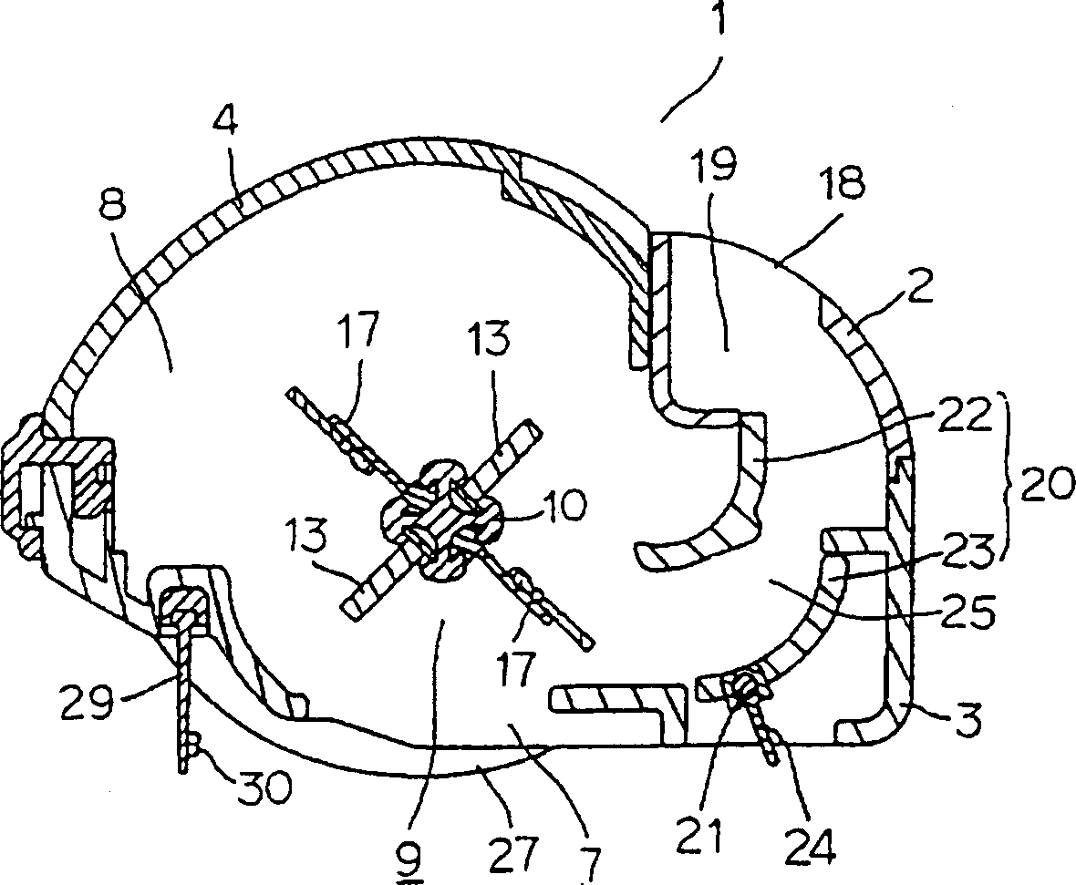
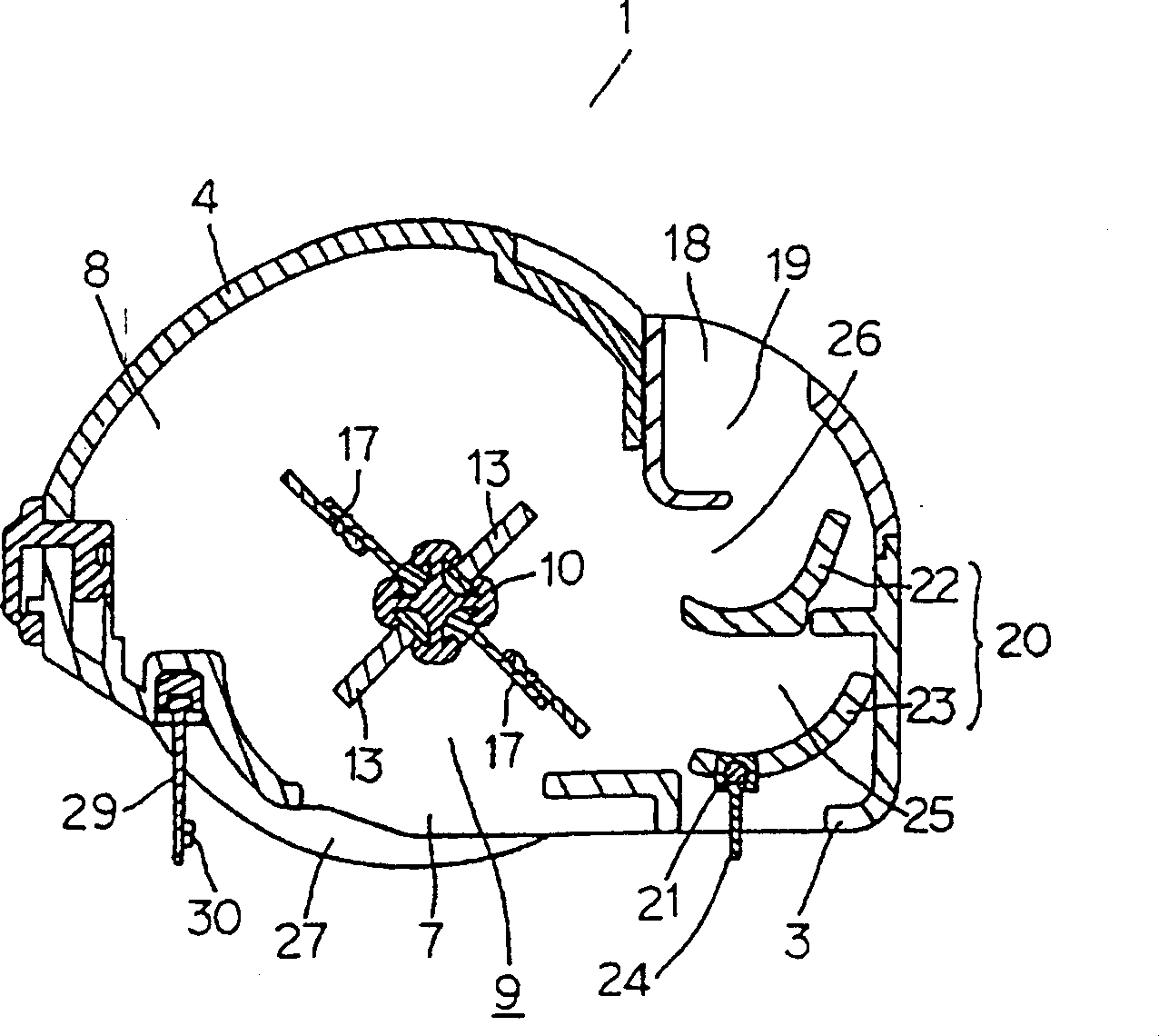
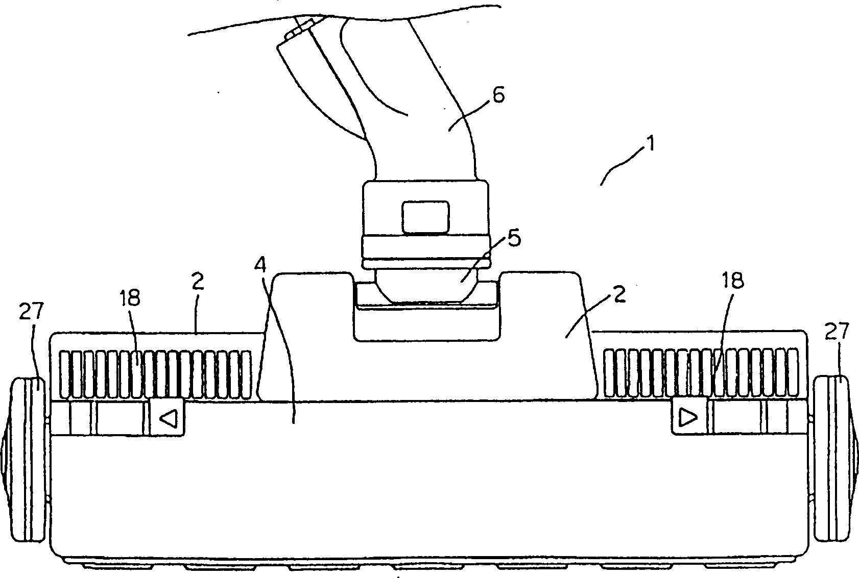
[0030] In the accompanying drawings, 1 is the main body of the vacuum cleaner, which is supported between the upper and lower shells 2 and 3 by the upper shell 2, the lower shell 3, and the cover body 4 that is fastened to the aforementioned upper shell 2 and the lower shell 3 and can be disassembled arbitrarily. And it consists of the rotating pipe 5 which can rotate arbitrarily in an up-down direction, and the connecting pipe 6 supported by this rotating pipe 5 and which can rotate arbitrarily. 7 is a suction port formed on the bottom surface of the aforementioned dust collector body 1, and 8 is a rotating brush storage chamber formed in the aforementioned dust collector body 1. 9 is a rotating brush that is housed in the rotating brush storage chamber 8 in a freely rotatable state facing the aforementioned suction port 7. The rubber-made first vane 13 attached to the helical groove 11 of the core 10, and a pair of second vanes 15 having a base 14 inserted into the helical g...


PUM


Abstract

To efficiently drive a rotary brush by a simple configuration by forming an intake path in a rotary brush storing chamber and providing a guide member having a blade part, which is moved in accordance with the progress direction of a sucking tool main body and which changes the direction of outer air to be guided from the intake path to blades in the intake path. When the sucking tool main body 1 is moved at the time of cleaning a carpet or the like, a suction keeper 24 is moved backward, the guide member 20 is rocked, a communication path 25 formed between first and second blade pieces 22 and 23 is communicated with the intake chamber 19, outer air is guided from the intake path 18 to the blades 13 below a rotary shaft through the communication path 25 and the rotary brush 9 is rotated in the opposite direction of the progress one. Besides, when the main body 1 is moved backward, the suction keeper 24 is moved forward, outer air from the intake path 18 is guided above the rotary shaft and the rotary brush 9 is rotated in the opposite direction of the progress one. The blades 13 of the rotary brush 9 are erected by centrifugal force at the time of high speed rotation and brought into contact with a surface to be cleaned so that cleaning is efficiently executed by scraping-out dust or the like.

Description

technical field [0001] The invention relates to a floor vacuum cleaner which can be connected with an electric vacuum cleaner. Background technique [0002] Conventionally known vacuum cleaners for floors have a free-rotatable rotating brush pivotally supported on the main body of the vacuum cleaner, and a motor or a turbine (ta-bin) drives the rotating brush to rotate. However, the vacuum cleaner driven by the motor to rotate the rotating brush has the disadvantages of heavy vacuum cleaner body due to the motor, difficult operation during cleaning, increased number of parts, and poor assembly workability. [0003] In addition, for a vacuum cleaner whose rotating brush is driven by a turbine, the turbine is arranged in the turbine chamber that forms the suction passage between the suction port and the vacuum cleaner body, and the sucked air rotates with the dust. Therefore, after a long period of use, dust will accumulate in the turbine, causing the problem that the turbine...

Claims


Application Information

Patent Timeline
Patent Type & Authority Patents(China)
IPC IPC(8): A47L9/02A47L9/04
CPCA47L11/204
Inventor 森好弘丰冈贤次
Owner SANYO ELECTRIC CO LTD
Why Eureka
Try Eureka