Embossing belt for parer machine

An embossing belt and paper machine technology, applied in the field of embossed paper manufacturing, can solve the problems of low dehydration capacity in the nip, low solid content of paper sheets, low production efficiency of paper machines, etc., and achieve high paper embossing effect

Inactive Publication Date: 2004-05-26
ALBANY INT AB
View PDF13 Cites 0 Cited by
  • Summary
  • Abstract
  • Description
  • Claims
  • Application Information

AI Technical Summary

Problems solved by technology

The disadvantage of these patented paper machines is that the dewatering capacity of the press nip is rather low, so that when the sheet is transferred to the drying cylinder, the solid content of the

Method used


Image

  • Embossing belt for parer machine
  • Embossing belt for parer machine
  • Embossing belt for parer machine

Examples


Embodiment Construction

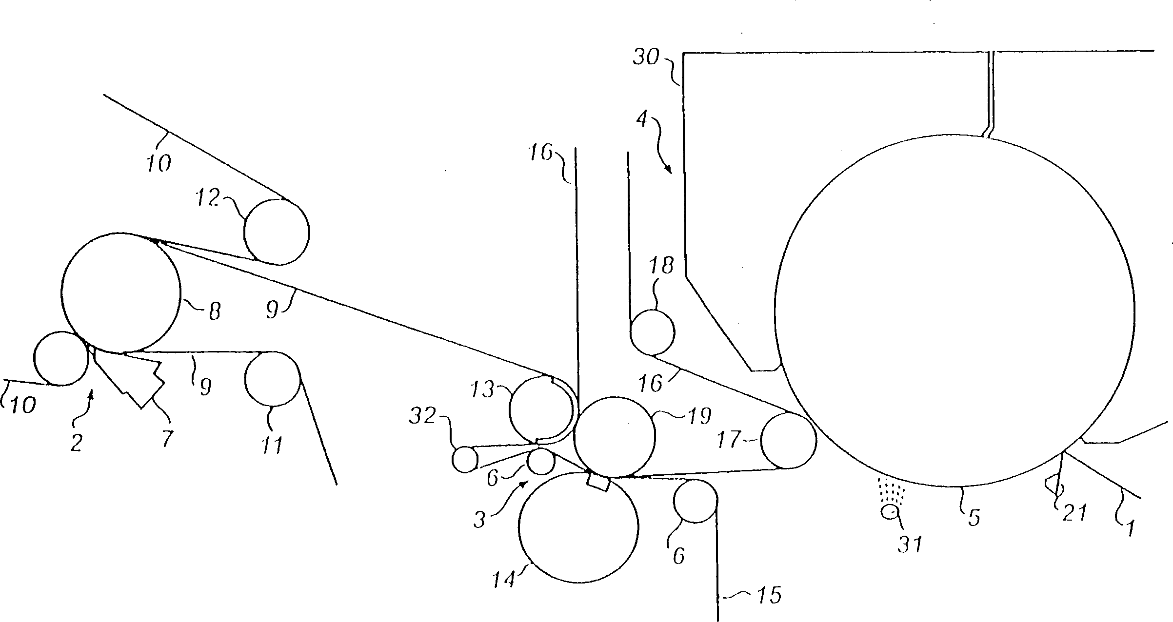
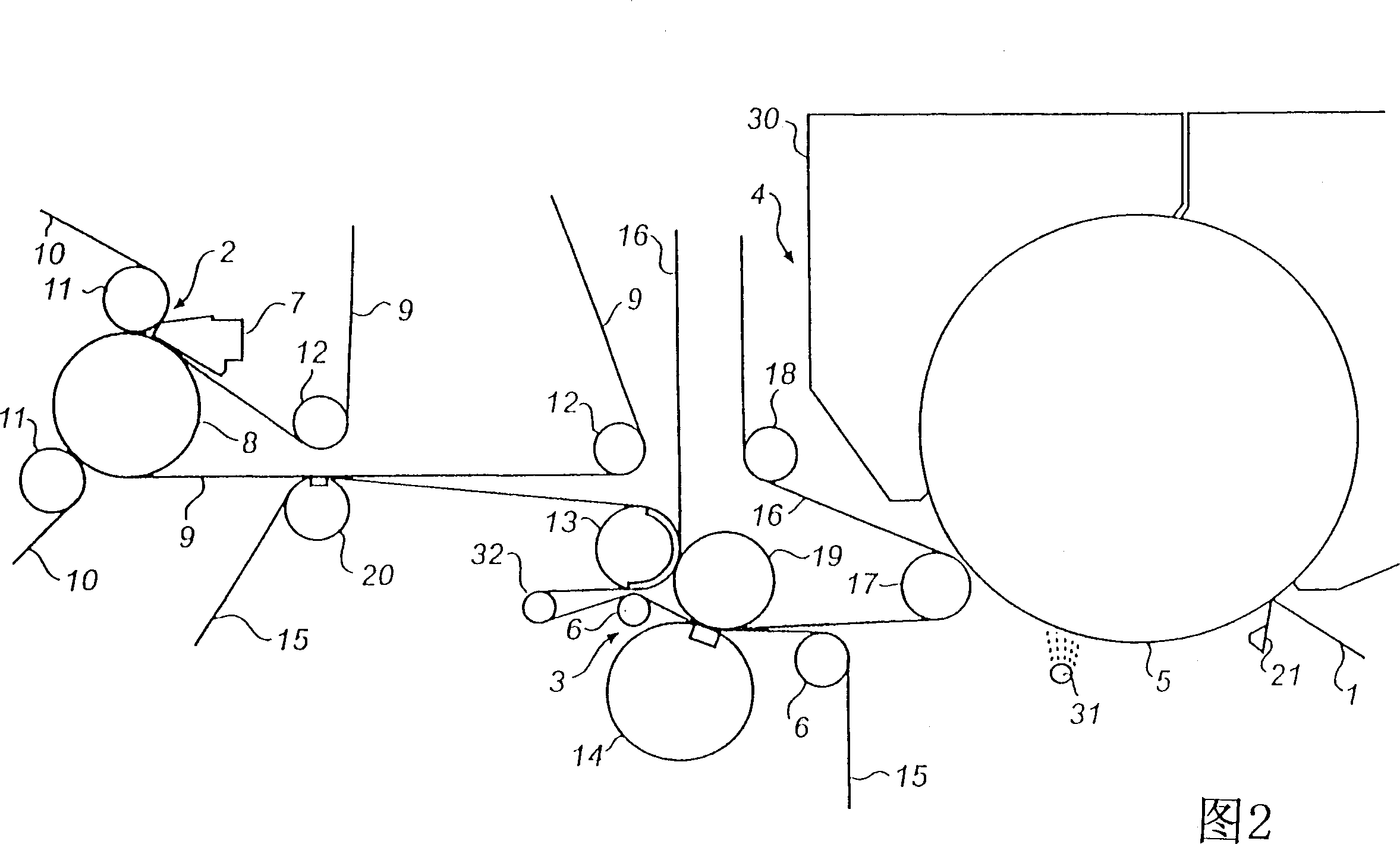
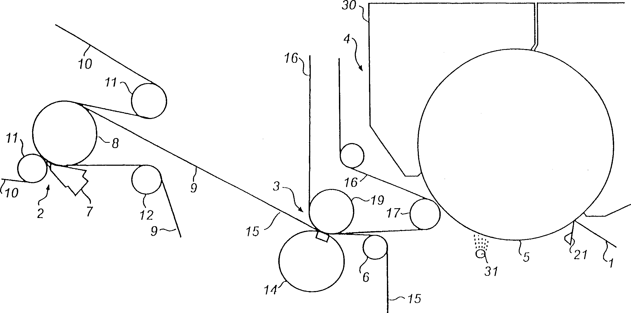
[0029] Figure 1-3 is a schematic diagram of the parts of a paper machine for making embossed fibrous sheets 1 of soft tissue paper, such as toilet paper. Each paper machine consists of a wet section 2 , a press section 3 and a dryer section 4 .

[0030] The wet end 2 comprises a headbox 7, a forming roll 8, an endless supporting inner felt 9 and an endless covering outer felt 10 consisting of a forming fabric. Inner and outer felts 9,10 all run around a plurality of guide rollers 11,12 in a loop.

[0031] The drying section 4 comprises a Yankee dryer 5 which is covered by a hood 30 . On the outlet side of the dryer section there is a creping doctor 21 for creping the fibrous sheet 1 coming from the Yankee dryer 5 . There is also a glue application device 31 for applying suitable glue to the peripheral surface of the Yankee dryer 5 before the transfer gap.

[0032] The press section 3 comprises a shoe press with a shoe press roll 14 and a support roll 19, said rolls 14, 19...


PUM

PropertyMeasurementUnit
Roughnessaaaaaaaaaa
Depthaaaaaaaaaa

Abstract

An embossing belt for a paper machine, intended to run through a press section in the paper machine together with a fibrous web and produce an embossment thereof in the press section, and to transfer the embossed fibrous web from the press section directly to and through a transfer means in the dryer section of the paper machine. The embossing belt is essentially impermeable and comprises a rear layer (33) and a web-contacting layer (34), which has a large number of uniformly distributed depressions (35) and, positioned therebetween, surface portions (36) for forming a corresponding relief pattern in the fibrous web passing through the press section.

Description

technical field [0001] The present invention relates to an embossed belt of a paper machine for the manufacture of embossed paper. Background technique [0002] DE-195 48 747 discloses a paper machine for the manufacture of creped tissue paper, which has a press comprising a shoe press roll, a support roll and a suction roll, the support roll and suction roll forming a first nip, It forms a second wide nip with shoe press rolls. A felt passes through two nips with the sheet, which then passes the sheet to the Yankee dryer—when the felt and sheet pass around guide rolls (the guide roll and the Yankee form the non-nip ), the sheet is conveyed to the Yankee dryer. Before and after the first nip, there is a water absorption area for dehydrating the felt. The water absorption area before the nip is located in the suction roll, and the water absorption area after the nip is located in the secondary loop. The felt runs along this loop alone, and in the second The nip entrance me...

Claims


Application Information

Patent Timeline
IPC IPC(8): D21F3/00D21F7/08D21F9/00D21F11/00D21F11/14
CPCD21F11/14D21F9/003D21F11/006Y10S162/901Y10S162/90Y10S162/902Y10T442/3707
Inventor 约兰·尼尔松布-克里斯特·奥贝里
Owner ALBANY INT AB
Why Eureka
Try Eureka