Fiber optic grating transverse strain sensor system
A technology of transverse stress and grating, applied in the direction of converting sensor output, using optical devices to transmit sensing components, instruments, etc., can solve problems such as poor configuration of optical fiber sensors, limited use, and lack of compensation for temperature drift
- Summary
- Abstract
- Description
- Claims
- Application Information
AI Technical Summary
Problems solved by technology
Method used
Image
Examples
Embodiment Construction
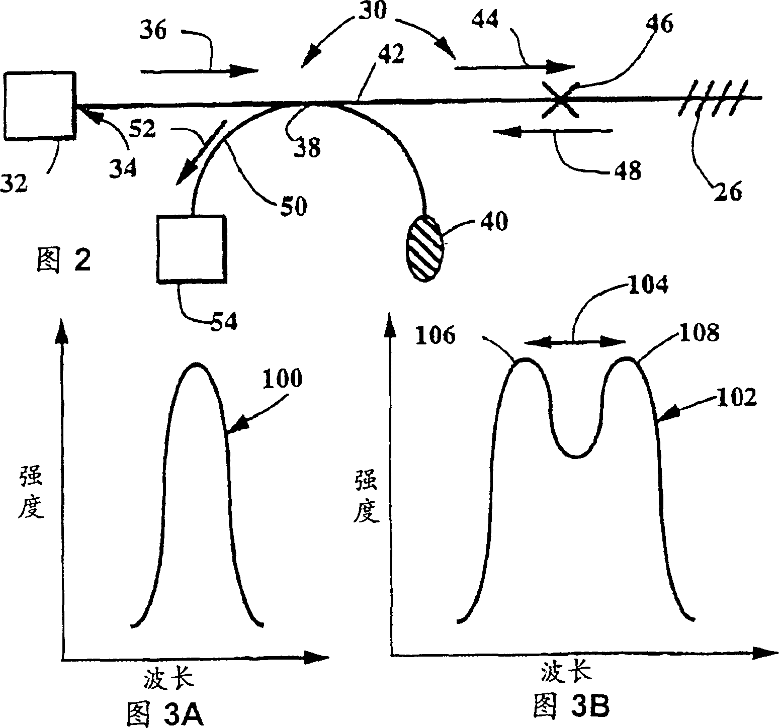
[0064]Referring to the drawings, and especially to the reference numerals, 22 in FIG. 1 refers to a circularly symmetrical single-mode optical fiber. Written on the fiber core 24 is a fiber grating 26 . When a FBG 26 is connected to a FBG demodulation system 30, as shown in FIG. 2, changes in the FBG period caused by environmental changes such as strain and temperature can be measured by measuring the light Spectrum shift to determine. In the case of the demodulation system shown in FIG. 2 , a broadband light source such as a light emitting diode or a relatively narrowband tunable light source 32 is used to couple light into the fiber end face 34 . The coupled beam 36 then passes through a beam splitter, such as a fiber optic splitter 38 . One port of the fiber splitter 38 can be terminated with an areflective end 40 or it can be used to support measurements on additional fiber gratings. A portion of beam 36 is split into output port 42 of beam splitter 38 as beam 44 . The...
PUM
 Abstract
Description
Claims
Application Information
 - R&D
- Intellectual Property
- Life Sciences
- Materials
- Tech Scout
- Unparalleled Data Quality
- Higher Quality Content
- 60% Fewer Hallucinations
Browse by: Latest US Patents, China's latest patents, Technical Efficacy Thesaurus, Application Domain, Technology Topic, Popular Technical Reports.
© 2025 PatSnap. All rights reserved.Legal|Privacy policy|Modern Slavery Act Transparency Statement|Sitemap|About US| Contact US: help@patsnap.com


