
Method and apparatus for identifying hardware

A technology of equipment and analog devices, applied in the field of data processing systems, which can solve problems such as changing system parameters

Inactive Publication Date: 2004-07-14
IBM CORP
View PDF0 Cites 0 Cited by
  • Summary
  • Abstract
  • Description
  • Claims
  • Application Information

AI Technical Summary

Problems solved by technology

Problems similar to OEM problems caused by new and improved parts from third-party manufacturers in that system parameters must be changed in order to introduce new parts

Method used


Image

  • Method and apparatus for identifying hardware
  • Method and apparatus for identifying hardware
  • Method and apparatus for identifying hardware

Examples


Embodiment Construction

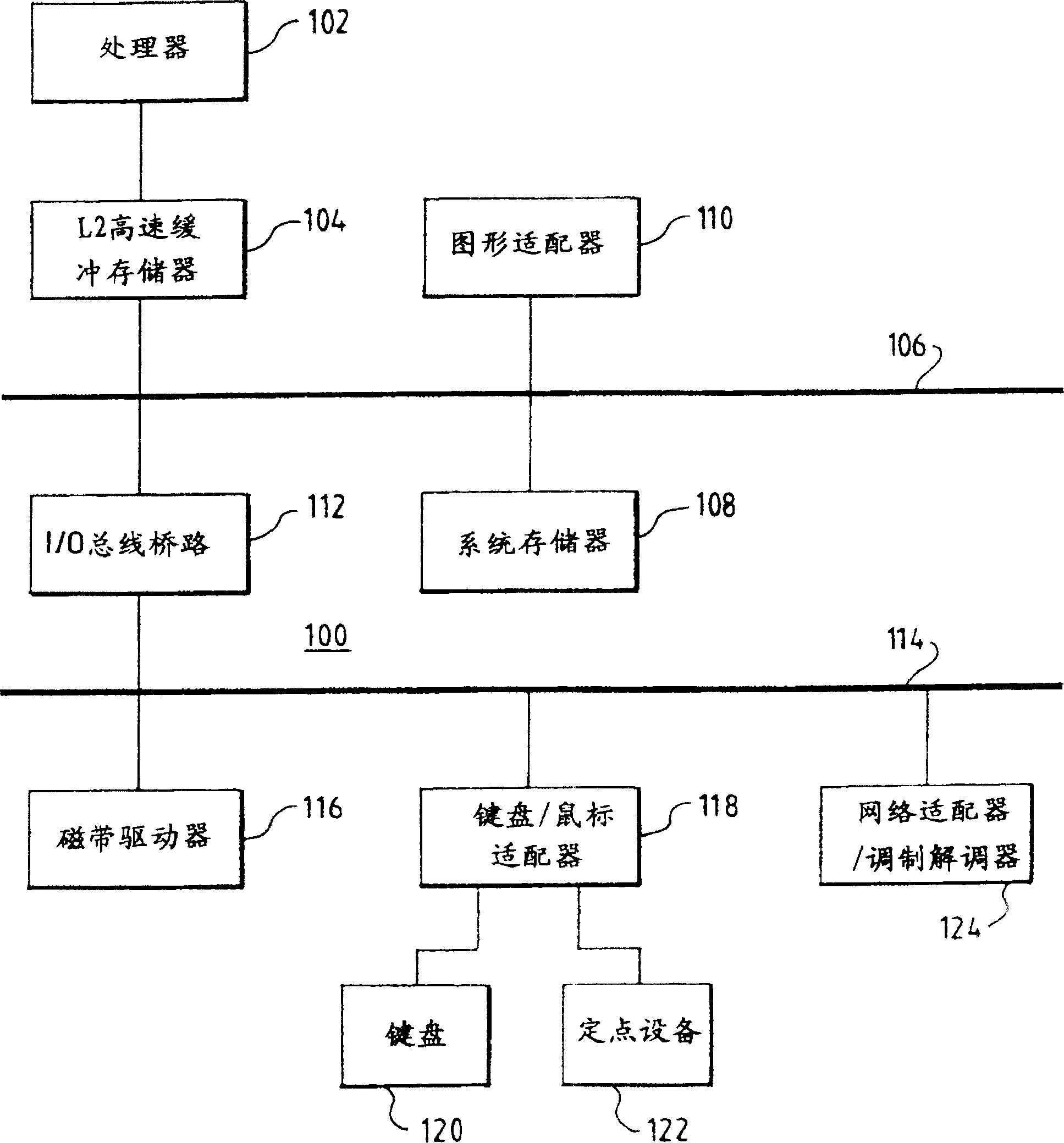
[0019] see figure 1 , which depicts a high-level flow diagram of a data processing system in which preferred embodiments of the present invention are implemented. Data processing system 100 in the exemplary embodiment includes processor 102, which may be, for example, a PowerPC processor available from International Business Machines Corporation of Armonk, New York. TM processor. The processor 102 is connected to a second level (L2) cache memory 104 for transferring data to or from the processor 102 with reduced access execution times. L2 cache memory 104 is in turn connected to interconnect or system bus 106 which is also connected to system memory 108 and memory-mapped graphics adapter 110 . Graphics adapter 110 provides a connection for a display (not shown) on which a user interface for software executing within data processing system 100 is displayed.

[0020] Also connected to system bus 106 is input / output (I / O) bus bridge 112 , which provides an interface between sy...


PUM


Abstract

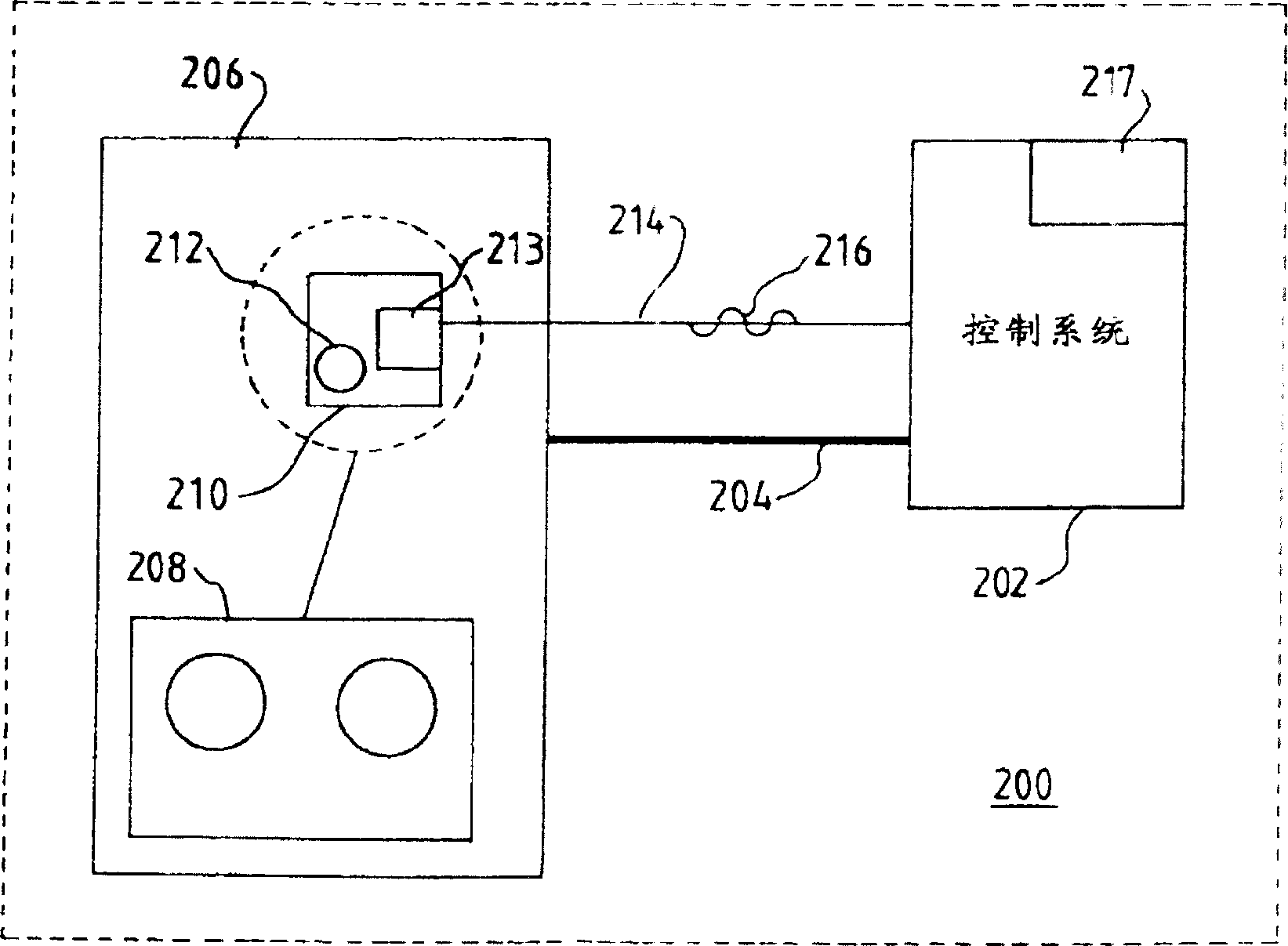
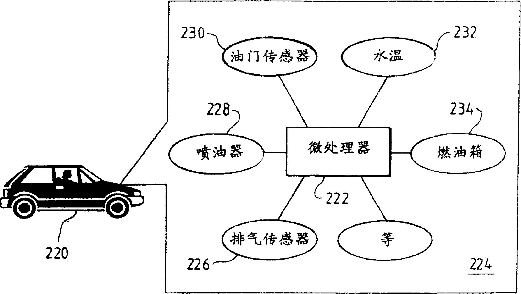
A microprocessor (digital device) with microcode is incorporated in a mechanical device, having analog electrical signaling wires, to send a digital signal containing identifying data of the device to a central computer. The digital signal includes operating ranges and any other information that will allow the central computer system to recognize the mechanical device and automatically incorporate the device's operating characteristics into the total system without disruption. The digital signal is transmitted to the central computer system immediately after a power-on signal is detected by the microprocessor on board the mechanical device.

Description

technical field [0001] This invention relates to data processing systems, and more particularly to identifying analog devices. Background technique [0002] It is common practice in the industry for original equipment manufacturers (OEMs) to rely on third-party vendors for spare parts for computer-related systems. OEMs provide standards for manufacturing spare parts to third party manufacturers, and often, OEMs supply spare parts to consumers. However, due to price, consumers will often purchase and install "equivalent" spare parts. "Equivalent" spare parts may be approved by the OEM for replacement, but "equivalent" spare parts do not carry out the same quality control requirements of the OEM. Spare parts may not be to OEM specifications and installation services are required to reconcile the spare part with the control system. In addition, OEMs may update or improve spare parts so that spare parts perform the same tasks as the original parts, but the tolerances or speci...

Claims


Application Information

Patent Timeline
Patent Type & Authority Patents(China)
IPC IPC(8): G06F13/10G06F11/22
CPCH05K999/99G06F11/2289
Inventor 亚历克斯·奇利文尼马克·爱德华·希尔
Owner IBM CORP
Learn More