Method for lapped joint or anchoring of reinforcing bars in reinforced concrete member

A reinforced concrete and steel bar anchoring technology, which is applied in the direction of building structure, construction, etc., can solve the problems of complex construction, large lap (connection) length, difficulty, etc., to reduce the length of lap or anchorage, and reduce the problem of staggered lap , Improve the effect of anchoring ability

Inactive Publication Date: 2004-08-11
NORTHERN ENG DESIGN & RES INST CO LTD
View PDF0 Cites 0 Cited by
  • Summary
  • Abstract
  • Description
  • Claims
  • Application Information

AI Technical Summary

Problems solved by technology

According to this requirement, the length of the lap (connection) is large, the construction is complicated, the positioning of the steel bar is difficult, and the binding connection is difficult.
[0003] In multi-wall buildings such as CL system, when the steel bar (wire) in the reinforced concrete shear wall is connected with the hidden column (beam), it is very difficult for the steel bar in the wall to extend into the hidden column (beam). , according to the standard staggered overlapping requirements, longer steel bars need to be overlapped several times, resulting in too long steel bars and disorderly

Method used


Image

  • Method for lapped joint or anchoring of reinforcing bars in reinforced concrete member
  • Method for lapped joint or anchoring of reinforcing bars in reinforced concrete member

Examples


Embodiment 1

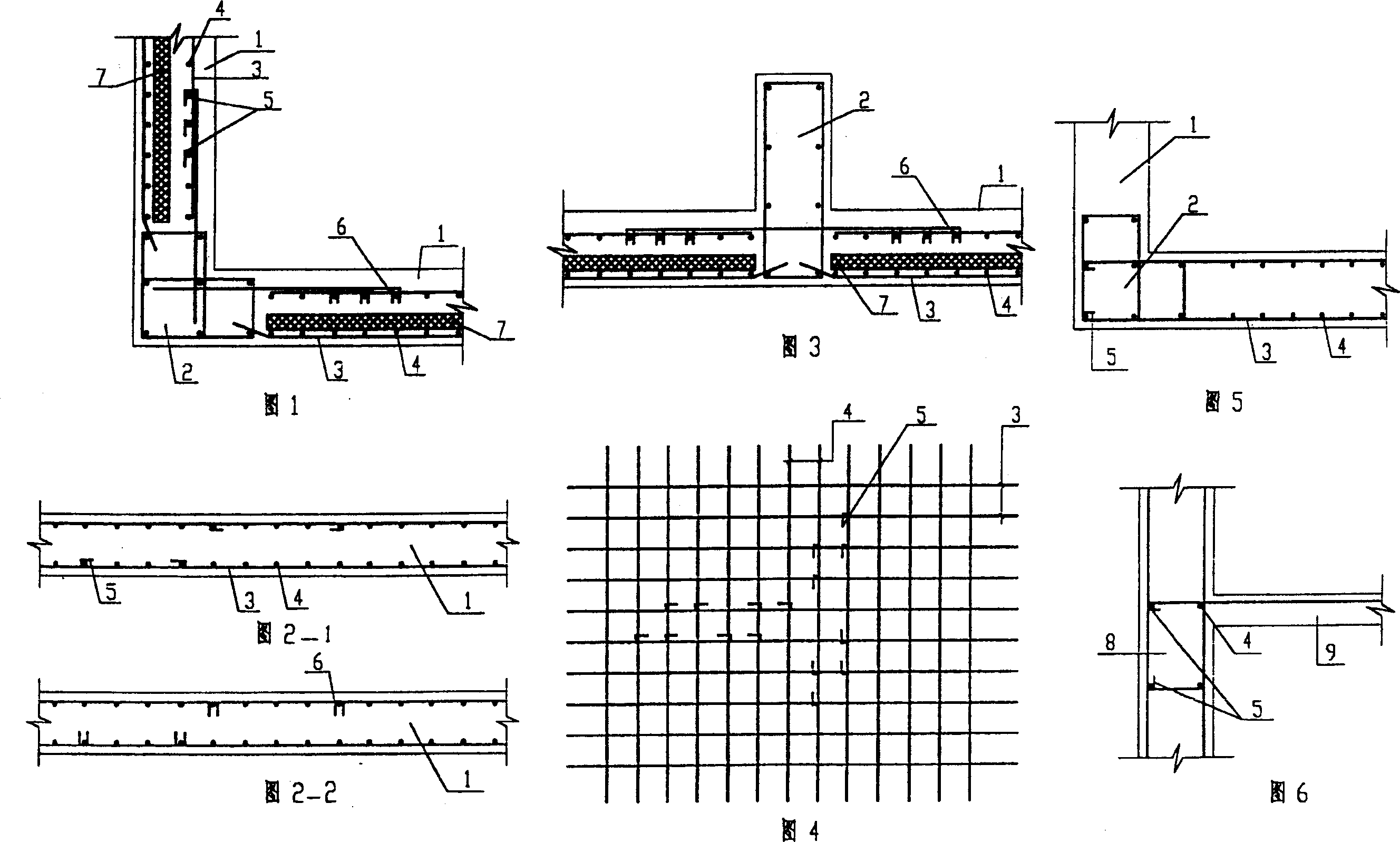
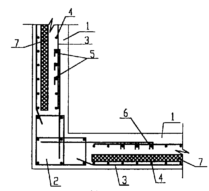
[0021] Embodiment 1: Using hooks or hooks to connect steel bars in reinforced concrete members (see Figures 1-4):

[0022] When the steel bars or steel wires in the reinforced concrete wall need lap joints, on the basis of the steel bar binding or welded mesh constructed earlier, use the lapped steel bars or steel wires with hooks or clips at the ends to hook or clamp the vertical longitudinal , horizontal steel bars or steel wires, so that the vertical and horizontal steel bars or steel wires are organically integrated.

[0023] When the steel bars are lapped, the overlapping steel bars with hooks or clips at the adjacent ends adopt the form of staggered lap joints.

[0024] The overlapping steel bars or steel wires with hooks or clips have 1-3 hooks or clips at the ends.

Embodiment 2

[0025] Embodiment 2: Adopting the method of anchoring the steel bar with a hook or clip in the reinforced concrete member (see Fig. 5, Fig. 6):

[0026] When the steel bar or steel wire in the reinforced concrete wall needs to be anchored in the beam or column, use the anchor steel bar or steel wire with hook or card at the end to hook or clamp the vertical steel bar in the beam, column or hidden beam, hidden column or Wires that integrate anchor bars or wires with vertical bars or wires in beams or columns.

[0027] An anchoring steel bar or steel wire with hooks or clips at the end, the number of hooks or clips at the end is 1-2.

Embodiment 3

[0028] Embodiment 3: In the reinforced concrete member, the method of combining the lap joint and anchorage of the hook or clamp is adopted, that is, when the steel bars in the reinforced concrete wall need lap joints, the lap joint method described in the invention is adopted. And when the steel bar in the reinforced concrete wall needs to be anchored in the beam or column, the anchoring method of the present invention is adopted.


PUM


Abstract

A method for lapping or anchoring of reinforcing bars in reinforced concrete member is disclosed. It is suitable for the shear wall, shear structure and multi-wall building. It is characterized by that one or more hooks or anchor clips are welded to the end of the reinforcing bars in wall, beam or pile in order to joint the vertical reinforcing bars with it easily and firmly. Its advantages are saving raw material, and simple construction.

Description

technical field [0001] The invention relates to a steel bar overlapping and anchoring method in a reinforced concrete component, which is suitable for a reinforced concrete shear wall structure, a frame shear structure, and reinforced concrete multi-wall buildings such as CL systems. Background technique [0002] At present, there are two types of lapping (connecting) of steel bars in ordinary reinforced concrete shear walls and reinforced concrete frame shear walls: one is binding and lapping; the other is mechanical connection or welding. Among them, class I steel bars are added with hooks, but not connected with other steel bars. The binding lap joints of adjacent longitudinally stressed steel bars in the same member should be staggered from each other, and meet the lap length and range required by the code, and it is required to bind the area percentage of the tensile steel bar lap joints in the same connection section of the board wall. It should not be greater than 25...

Claims


Application Information

Patent Timeline
Patent Type & Authority Patents(China)
IPC IPC(8): E04B1/41
Inventor 张晓萌张洪波
Owner NORTHERN ENG DESIGN & RES INST CO LTD
Why Eureka
Try Eureka