
Alkaline storage battery with scroll electrode body

A scroll-shaped electrode body technology, which is applied to the conductive connection between the scroll-shaped electrode body and the metal outer can, and the conductive connection between the scroll-shaped electrode body and the current collector, which can solve the problem of reducing the operating voltage and current Problems such as uneven distribution and non-welding of the current collector for the negative electrode

Inactive Publication Date: 2004-08-25
FDK CORP
View PDF0 Cites 0 Cited by
  • Summary
  • Abstract
  • Description
  • Claims
  • Application Information

AI Technical Summary

Problems solved by technology

[0005] However, if the current collector for the negative electrode is made so large that it does not come into contact with the metal outer can, there will be a part where the current collector for the negative electrode is not welded on the welded part of the negative electrode plate and the current collector for the negative electrode.
If there is a part where the current collector for the negative electrode is not welded, the current distribution of the current collection path from the current collector for the negative electrode to the negative plate will become uneven, and a voltage drop will occur at the part where the current collector for the negative electrode is not welded
Although such a voltage drop does not become a big problem in the case of charging and discharging with a small current, in the case of charging and discharging with a large current of tens of amperes to hundreds of amperes, a large voltage drop is caused by the resistance of the above-mentioned connection part and thus Reduce the operating voltage, resulting in the problem of not being able to obtain a high voltage, resulting in the problem of reducing the high-rate discharge characteristics
In addition, since the reaction heat (endothermic reaction) of the nickel-metal hydride storage battery is smaller than that of the nickel-cadmium storage battery, the problem of increasing the temperature rise due to the influence of Joule heat and increasing the internal pressure during charging occurs.

Method used


Image

  • Alkaline storage battery with scroll electrode body
  • Alkaline storage battery with scroll electrode body
  • Alkaline storage battery with scroll electrode body

Examples


Embodiment 1

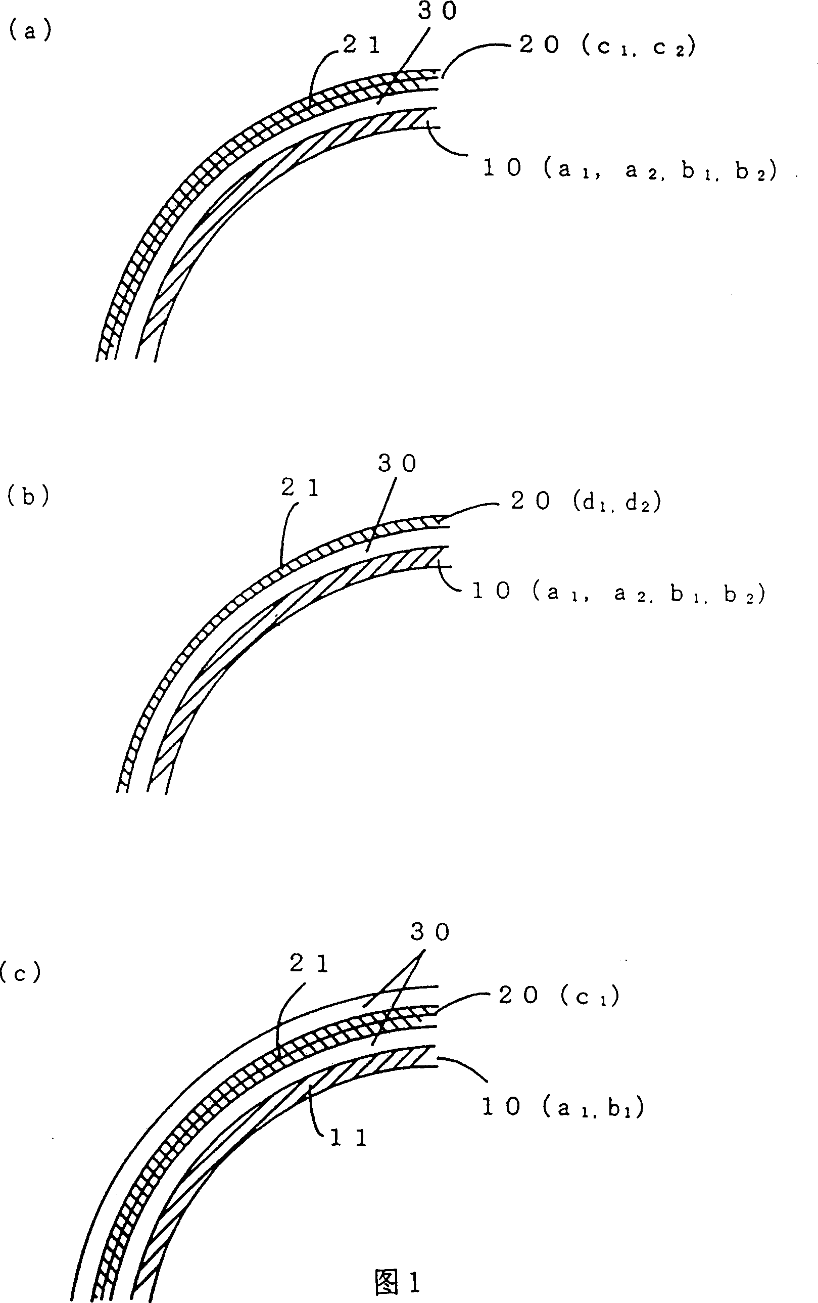
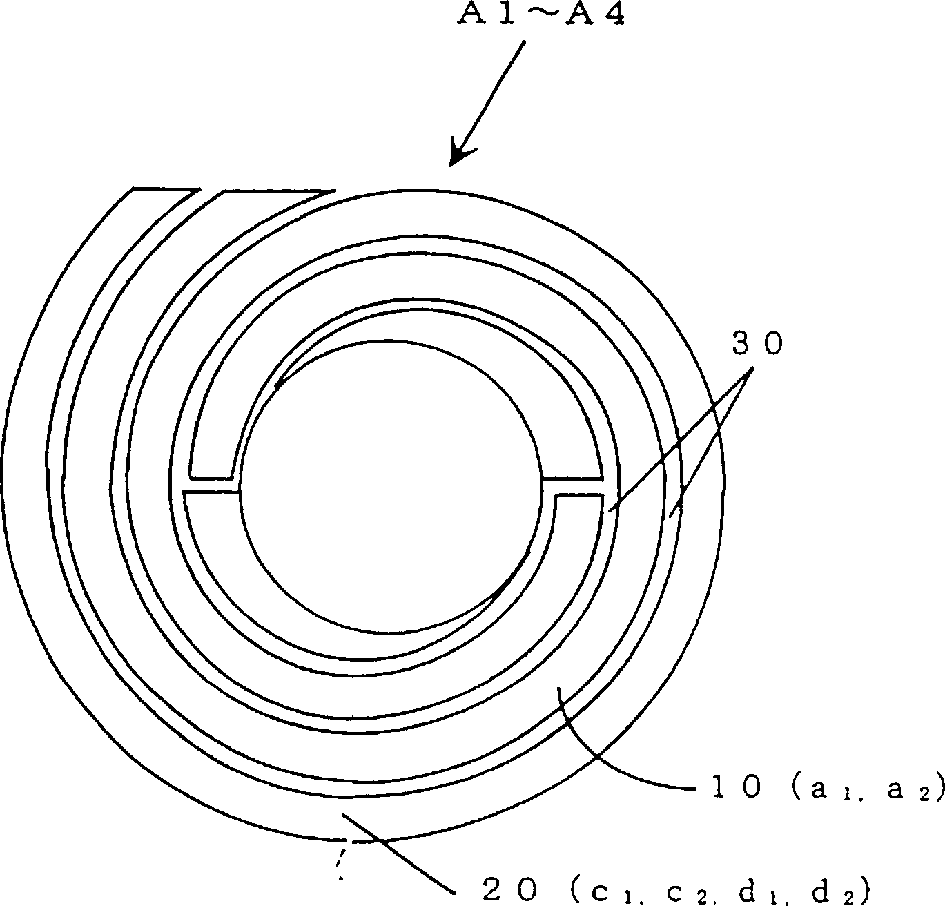
[0033] A separator 30 made of polypropylene non-woven fabric is placed between the sintered nickel positive electrode plate a1 and the hydrogen-absorbing alloy negative electrode plate c1 prepared above, and the upper end of the positive electrode plate a1 is lower than the upper end of the separator 30. protruding, the lower end of the negative plate c1 protrudes more than the lower end of the separator 30 for accumulation, and then uses a winding core not shown in the figure, as shown in Figure 1 (a) and figure 2 As shown, the negative electrode plate c1 is wound in a spiral shape on the outermost periphery to produce a spiral electrode group A1. The diameter of the spiral electrode group wound in a spiral shape in this way was about 22 mm. In addition, a negative electrode active material exists outside the core body of the negative electrode plate c1 on the outermost periphery of the spiral electrode group A1.

[0034] Thereafter, the lower end of the negative electrode p...

Embodiment 2

[0036] A separator 30 made of polypropylene non-woven fabric is placed between the sintered nickel positive electrode plate a1 and the hydrogen-absorbing alloy negative electrode plate d1 prepared above, and the upper end of the positive electrode plate a1 is lower than the upper end of the separator 30. protruding, the lower end of the negative plate d1 protrudes more than the lower end of the separator 30 for accumulation, and then adopts a winding core not shown in the figure, as shown in Figure 1(b) and figure 2 As shown, the negative electrode plate d1 is wound in a spiral shape on the outermost periphery to produce a spiral electrode group A2. The diameter of the spiral electrode group A2 wound in a spiral shape in this way is about 22 mm. In addition, no negative electrode active material exists outside the plate core of the negative electrode plate d1 on the outermost periphery of the spiral electrode group A2. Afterwards, the lower end of the negative electrode plate...

Embodiment 3

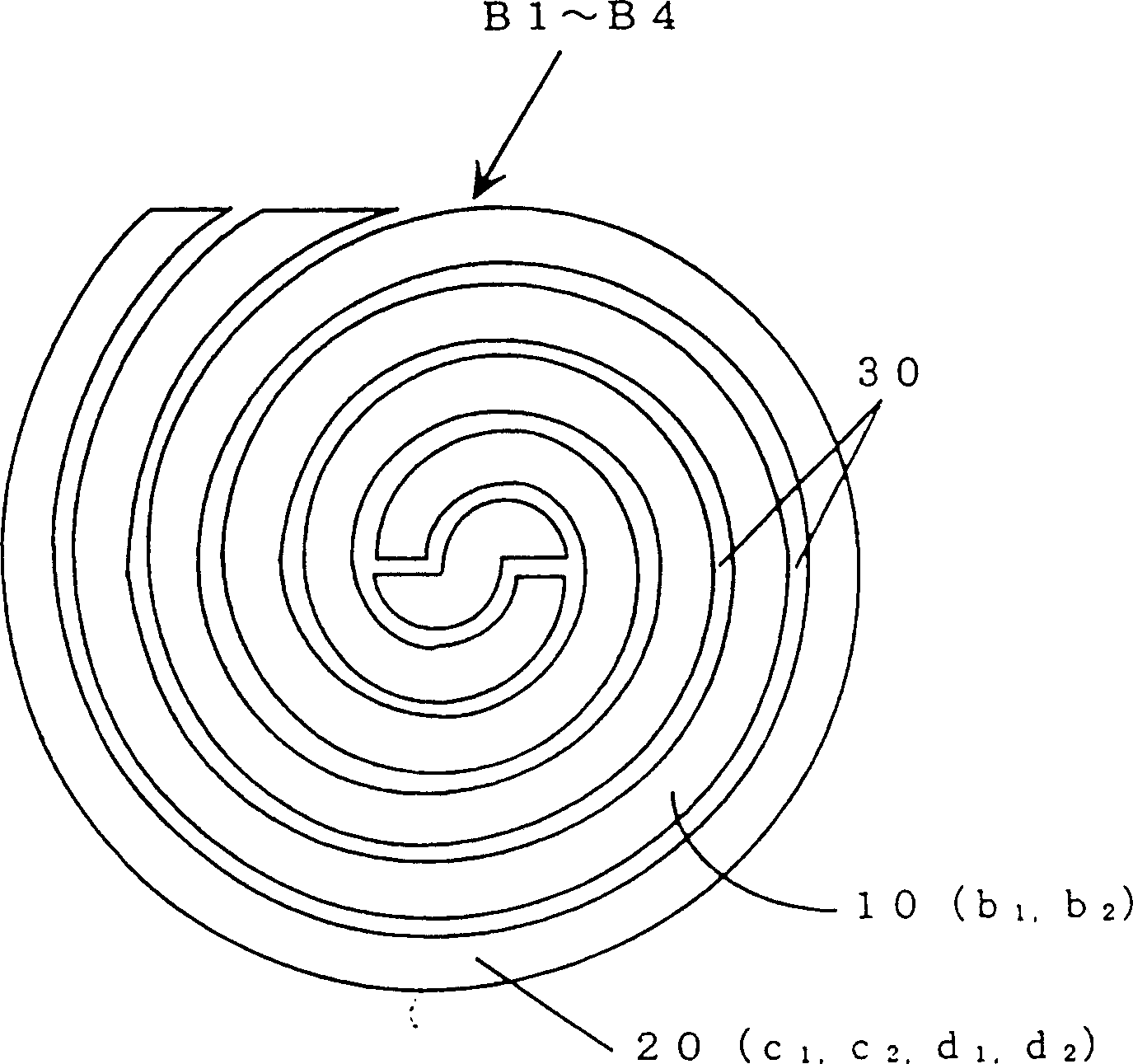
[0038] A separator 30 made of polypropylene non-woven fabric is placed between the sintered nickel positive plate a2 and the hydrogen-absorbing alloy negative plate c2 produced above, and the upper end of the positive plate a2 is lower than the upper end of the separator 30. protruding, the lower end of the negative plate c2 is more protruding than the lower end of the separator 30 for accumulation, and then adopts a winding core not shown in the figure, as shown in Figure 1 (a) and image 3 As shown, the negative electrode plate c2 is wound in a spiral shape on the outermost periphery to produce a spiral electrode group A3. The diameter of the spiral electrode group A3 wound in a spiral shape in this way is about 22 mm. In addition, a negative electrode active material exists outside the core body of the negative electrode plate c2 on the outermost periphery of the spiral electrode group A3. Afterwards, the lower end of the negative electrode plate c2 of the spiral electrode...


PUM

PropertyMeasurementUnit
Diameteraaaaaaaaaa
Diameteraaaaaaaaaa
Diameteraaaaaaaaaa

Abstract

An alkaline storage battery including a group of spiral electrodes composed of positive and negative electrode plates spirally wound with a separator interposed therebetween and contained in a metallic cell casing used as an external terminal wherein the group of spiral electrodes is formed at its central portion with a space defined by a winding core during the winding process of the electrode plates and is provided with a first current-collector welded to an upper end of one of the electrode plates and a second current-collector welded to a lower end of the other electrode plate, wherein the second current-collector is welded to an internal surface of the bottom of the cell casing without being welded to an end portion of the other plate located at the outermost periphery of the group of spiral electrodes, and wherein the other electrode plate at the outermost periphery of the group of spiral electrodes is pressed into contact with an internal peripheral wall of the cell casing.

Description

technical field [0001] The present invention relates to an alkaline storage battery with a scroll-shaped electrode body in which a separator is interposed between the positive and negative plates of a nickel-metal hydride storage battery, a nickel-cadmium storage battery, etc., and is particularly related to a scroll-shaped electrode body and The conductive connection between the current collectors and the conductive connection between the scroll-shaped electrode body and the metal outer can. Background technique [0002] Alkaline accumulators such as existing nickel-metal hydride accumulators, nickel-cadmium accumulators have, after intervening separator between positive and negative pole plate and being wound into the scroll-shaped electrode group of spiral shape, the positive plate of this scroll-shaped electrode group Weld the current collector for the positive electrode on the upper end of the spiral electrode group, weld the current collector for the negative electrode...

Claims


Application Information

Patent Timeline
IPC IPC(8): H01M2/26H01M10/28H01M10/34
CPCY02E60/124H01M10/286H01M10/345Y02E60/10Y02P70/50
Inventor 春日秀夫伊势忠司石丸顺康
Owner FDK CORP
Learn More