Hydraulic hammer with micro motion of lower hammer

A technology of hydraulic hammer and hammer head, applied in the field of die forging hydraulic hammer, can solve the problems of poor striking accuracy, inconvenient connection, slow striking speed, etc., and achieve the effect of fast striking speed, convenient connection and time saving.

Inactive Publication Date: 2004-09-15
太原重型机械学院
View PDF0 Cites 1 Cited by
  • Summary
  • Abstract
  • Description
  • Claims
  • Application Information

AI Technical Summary

Problems solved by technology

[0004] The purpose of the present invention is to solve the technical difficulties of inconvenient connection, slow striking speed and poor striking precision of the hammer body micro-lift hydraulic hammer, and to provide a micro-moving lower hammer head with convenient connection, fast striking speed and high striking precision. hydraulic hammer

Method used


Image

  • Hydraulic hammer with micro motion of lower hammer
  • Hydraulic hammer with micro motion of lower hammer

Examples


Embodiment Construction

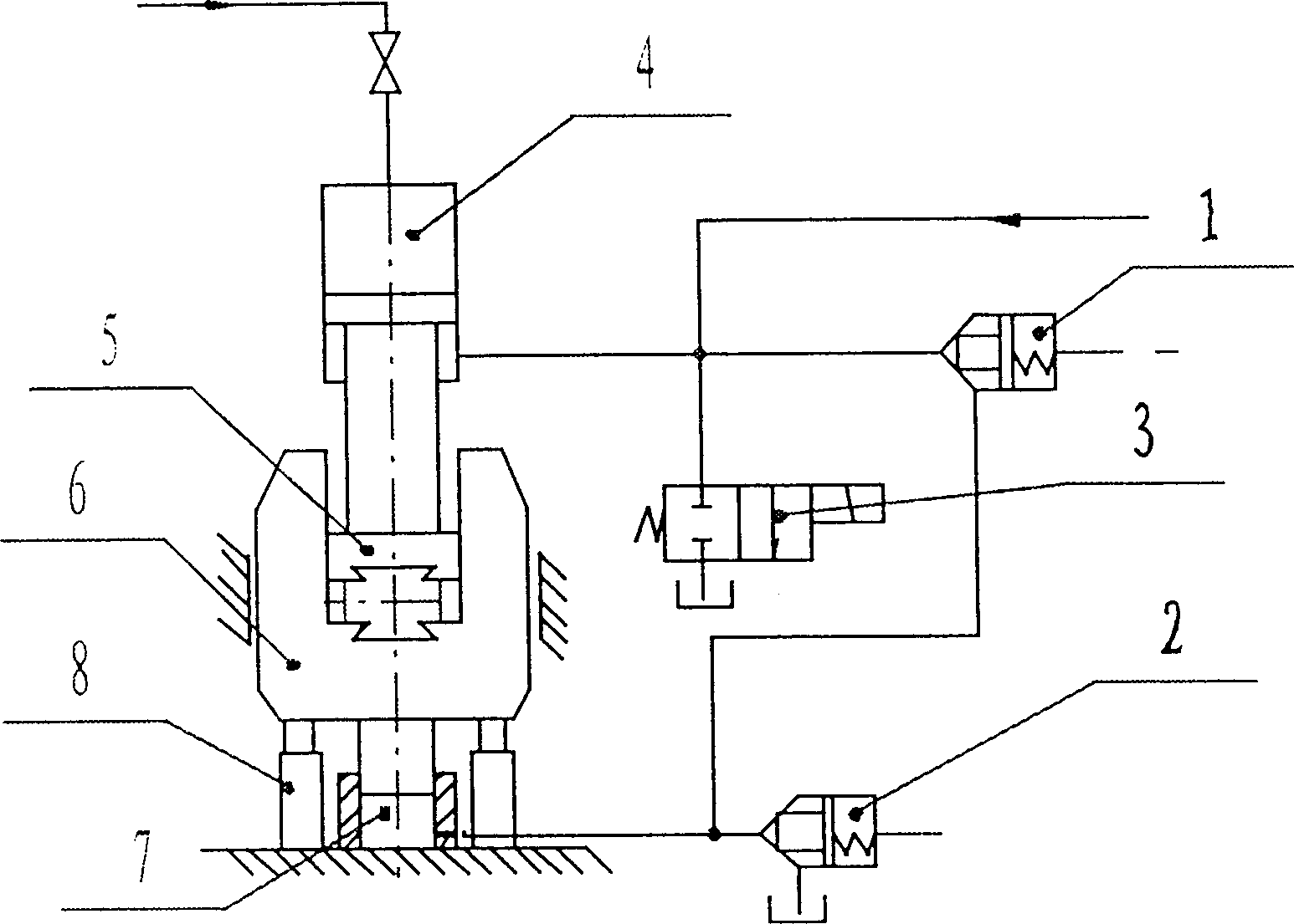
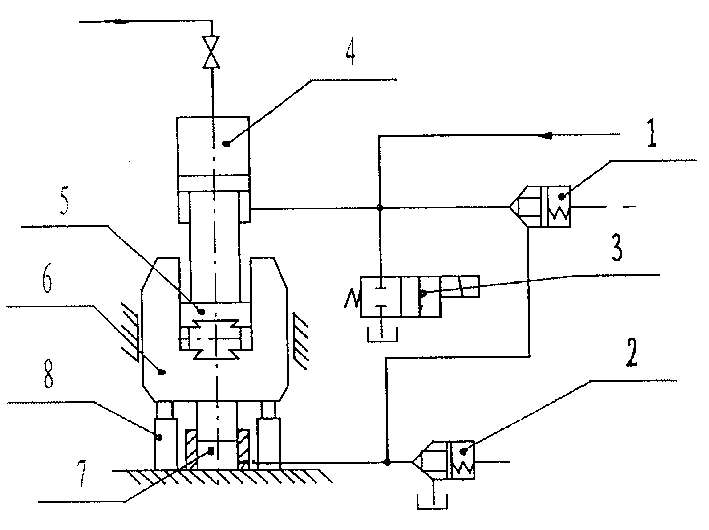
[0014] As shown in the drawings, the lower hammer head micro-motion hydraulic hammer in this embodiment includes an energy storage cylinder 4, an upper hammer head 5 and a U-shaped lower hammer head 6 located at the lower end of the piston rod of the energy storage cylinder 4 , the upper hammer head 5 is loaded into the U-shaped lower hammer head 6, wherein: it also includes an air cushion 8, a communication cylinder 7, and is composed of two two-way cartridge valves 1, 2, and a two-position two-way electromagnetic reversing valve 3 The driving device; the air cushion 8 is located on both sides of the bottom of the U-shaped lower hammer head 6, the communication cylinder 7 is located in the middle of the bottom of the U-shaped lower hammer head 6, and the plunger of the communication cylinder 7 is connected to the bottom surface of the U-shaped lower hammer head 6 , the oil inlet of the first two-way cartridge valve 1 is connected with the oil port of the lower cavity of the en...


PUM


Abstract

A hydraulic press with micromotion of lower hammer is composed of energy-accumulating working cylinder, upper hammer connected to lowr end of piston rod for said working cylinder, U-shaped lower hammer for recepting said upper hammer in its U recess, and drive unit consisting of air cushion at both sides of lower hammer, communicated cylinders under lower hammer, and valves. Its advantages are convenient connection and high beat speed and precision.

Description

1. Technical field: [0001] The invention relates to a micro-movement hydraulic hammer with a lower hammer head, which belongs to a die forging hydraulic hammer. 2. Background technology: [0002] Among the existing die forging equipment in our country, the steam-empty die forging hammer is one of the main equipment. Compared with other die forging equipment such as mechanical presses and friction presses, the steam-empty die forging hammer has a simple structure, low price, fast striking speed, many strokes, good forming technology, and does not require billet making equipment, so it is widely used , especially suitable for small and medium batch production plants. [0003] However, with the development of production, the problems exposed by the steam-air hammer have become more and more prominent. These problems are mainly manifested in: ① high energy consumption, extremely low thermal efficiency, and its effective energy utilization rate is less than 2%; ② high vibration...

Claims


Application Information

Patent Timeline
Patent Type & Authority Patents(China)
IPC IPC(8): B21J7/28
Inventor 李永堂朱元乾雷步芳巨丽
Owner 太原重型机械学院
Why Eureka
Try Eureka