

Liquid crystal display device
A technology of liquid crystal display device and liquid crystal display element, which is applied to identification devices, static indicators, optics, etc., can solve problems such as difficulty in reducing contrast ratio, easy blackening of displayed images, and blurred vision.
- Summary
- Abstract
- Description
- Claims
- Application Information
AI Technical Summary
Problems solved by technology
Method used
Image

Examples
Embodiment 1
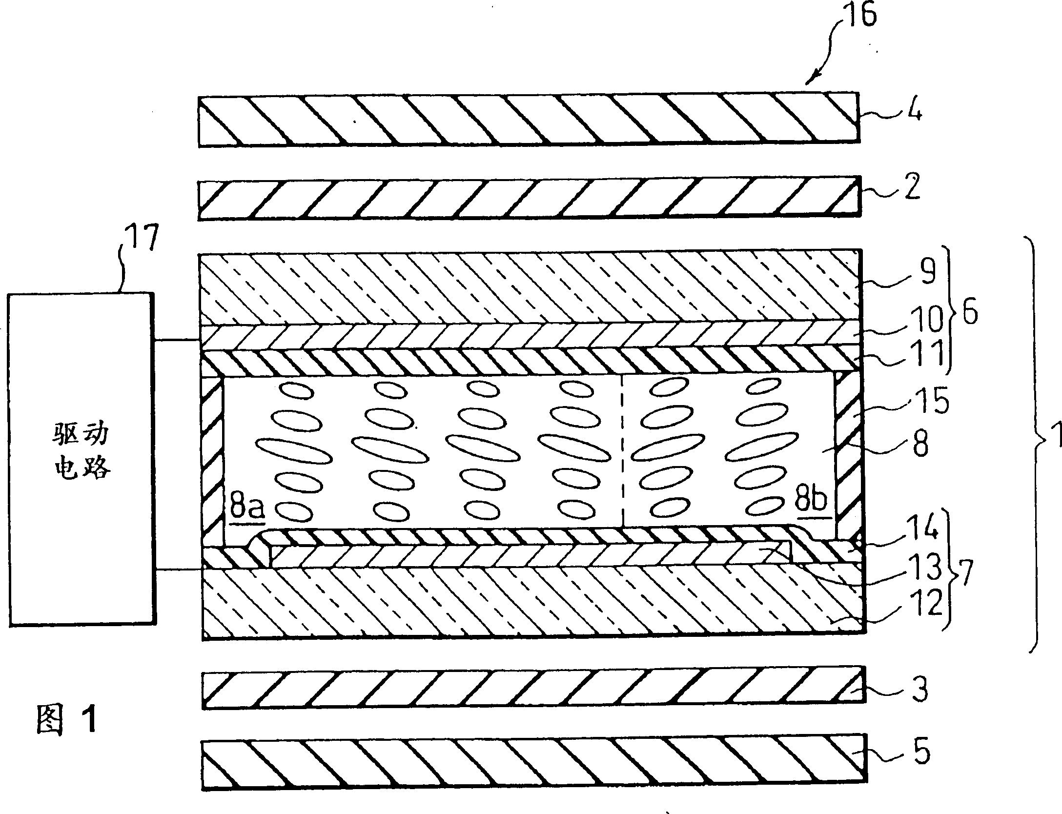
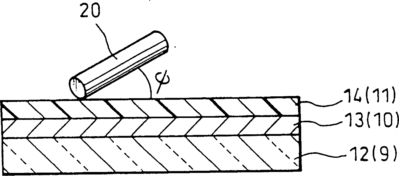
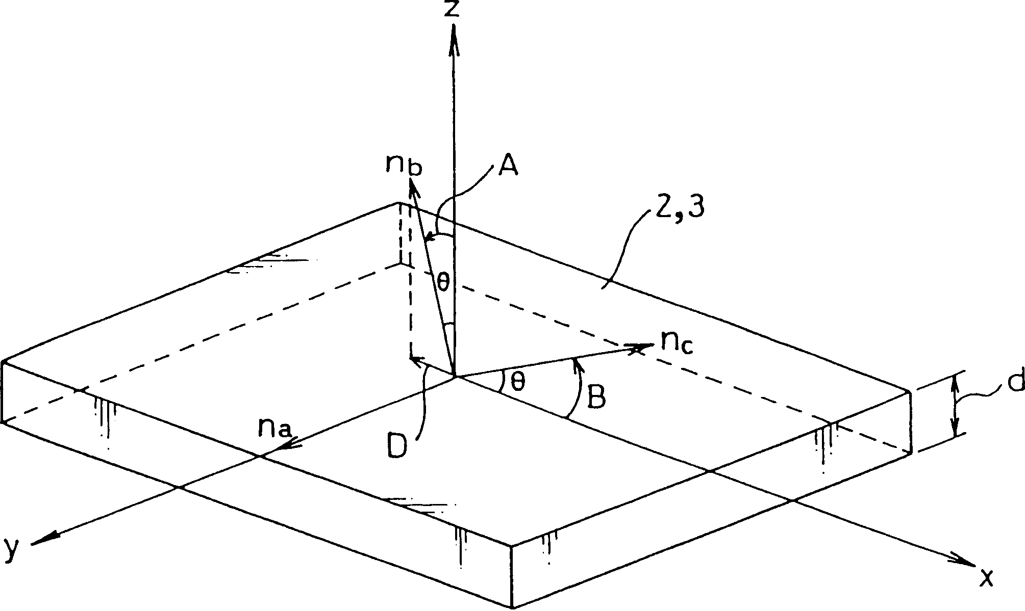
[0114] In this example, as shown in FIG. 6 , the viewing angle dependence of the liquid crystal display device was measured using a measurement system including a light receiving element 21 , an amplifier 22 and a recording device 23 . The liquid crystal cell 16 of the liquid crystal display device is installed so that the surface 16a on the side of the glass substrate 9 is located on the reference plane x-y of the orthogonal coordinates xyz. The light-receiving element 21 is an element capable of receiving light at a constant three-dimensional light-receiving angle, and is arranged at a predetermined distance from the coordinate origin in a direction forming an angle Φ (viewing angle) with respect to the z direction perpendicular to the surface 16a.
[0115]In the measurement, the liquid crystal cell 16 installed in the measurement system was irradiated with monochromatic light having a wavelength of 550 nm from the surface opposite to the surface 16 a. Part of the monochroma...
Embodiment 2
[0132] In the present embodiment, seven samples #11 to #17 were prepared. Among the samples, as the alignment films 11 and 14 of the liquid crystal cell 16 of the liquid crystal display device of FIG. Name), as the liquid crystal layer 8, adopted the liquid crystal material that is 2.0 °, 4.0 °, 6.0 °, 8.0 °, 14.0 °, 15.0 °, 16.0 ° with respect to the pretilt angle of above-mentioned alignment film 11,14, cell thickness ( The thickness of the liquid crystal layer 8) is 5 μm. The ratio of the first divided portion 8 a : the second divided portion 8 b of the liquid crystal layer 8 is assumed to be 17:3.
[0133] The measurement of the pretilt angles of these samples #11 to #17 was prepared by preparing homogeneous units filled with the materials of samples #11 to #17 and using an NSMAP-3000LCD pretilt angle measuring device (manufactured by Sigma Optical Equipment Co., Ltd.) measured.
[0134] As the optical retardation films 2 and 3 of the samples #11 to #17, the same optical...
Embodiment 3
[0202] In the present embodiment, prepared 3 samples #21~#23, in the sample as the orientation film 11,14 of the liquid crystal cell 16 of the liquid crystal display device of Fig. name), as the liquid crystal layer 8 (division ratio 17:3), the pretilt angle relative to the above-mentioned alignment films 11, 14 is 6°, and the refractive index anisotropy Δn(550) at a wavelength of 550 nm is set as For liquid crystal materials of 0.070, 0.080, and 0.095, the cell thickness (the thickness of the liquid crystal layer 8 ) is 5 μm.
[0203] In addition, the measurement of the pretilt angle prepared the homogeneous cell filled with the material of sample #21-#23, and measured it with NSMAP-3000 pretilt angle measuring apparatus.
[0204] As the optical retardation films 2 and 3 of samples #21 to #23, the same optical retardation films 2 and 3 in which disco-teik liquid crystals were obliquely oriented as in the above-mentioned Example 1 were used.
[0205] The above-mentioned sampl...
PUM
 Abstract
Description
Claims
Application Information