Image forming device and driving transmission device thereof

An image, clutch shaft technology, applied in transmissions, gear transmissions, electrical recording processes using charge graphics, etc., can solve the problem of troublesome replacement of the clutch, reduce the number of parts, prevent the clutch shaft from tilting, and easily replace the clutch. Effect

Inactive Publication Date: 2004-09-29
RICOH KK
View PDF0 Cites 0 Cited by
  • Summary
  • Abstract
  • Description
  • Claims
  • Application Information

AI Technical Summary

Problems solved by technology

[0010] However, if the cover member 15 is removed, for example Figure 11 As shown, the clutch shaft 11 is tilted from the state indicated by the dotted line to the state indicated by the solid line, and it is very troublesome to replace the clutch

Method used


Image

  • Image forming device and driving transmission device thereof
  • Image forming device and driving transmission device thereof
  • Image forming device and driving transmission device thereof

Examples


Embodiment Construction

[0046] Embodiments of the present invention will be described in detail below with reference to the accompanying drawings.

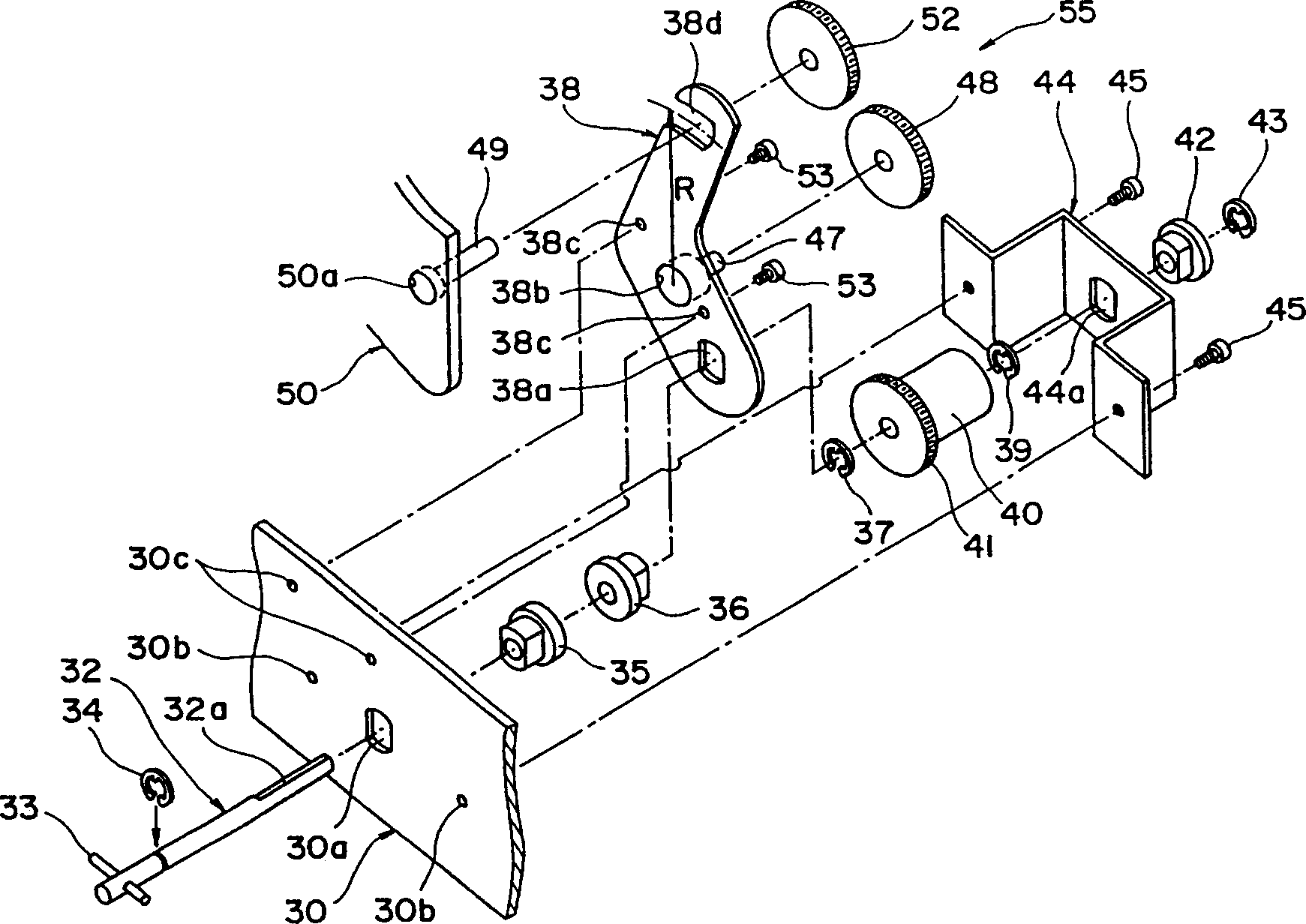
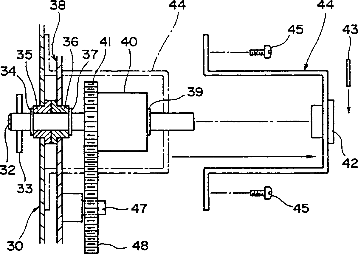
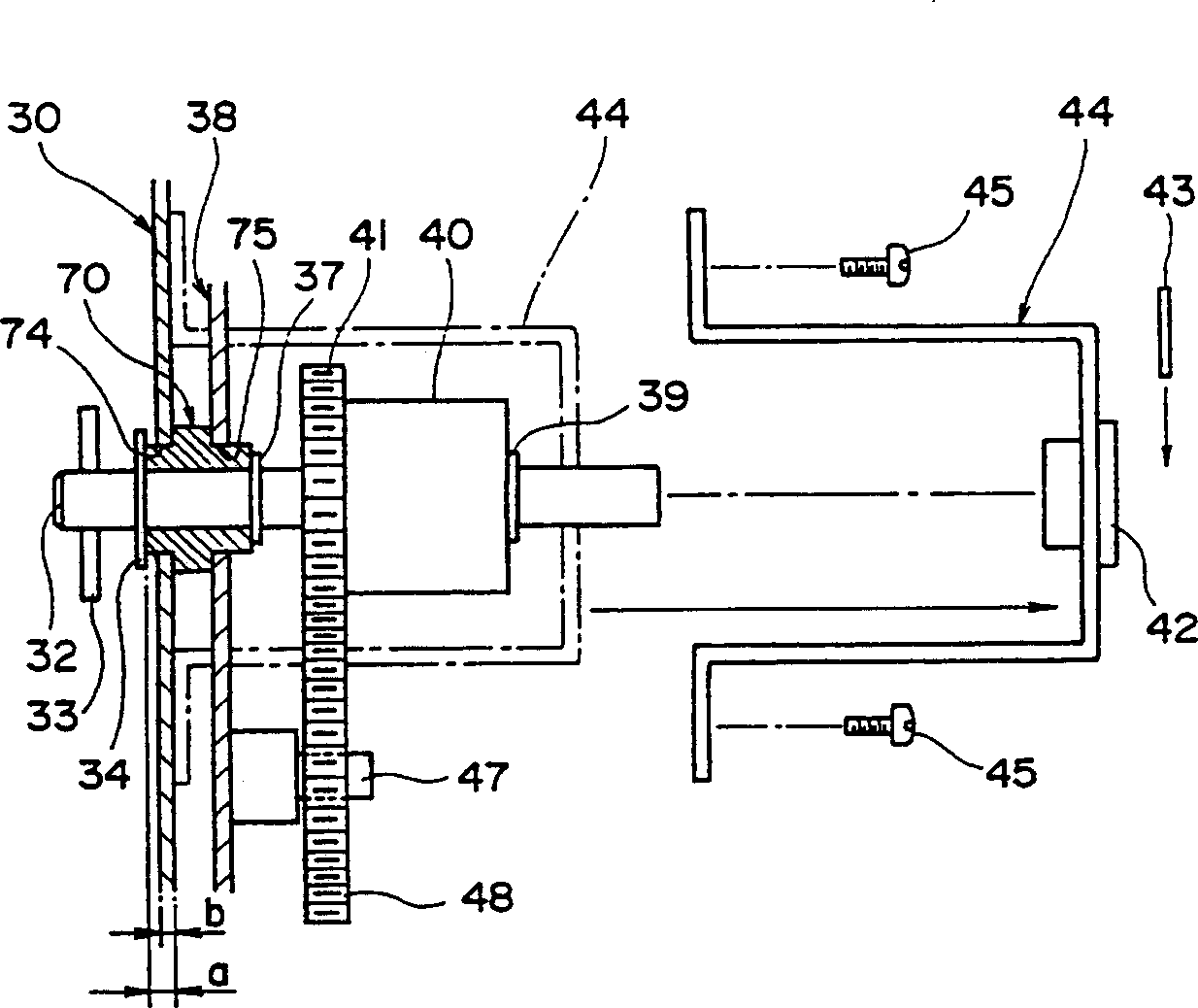
[0047] figure 1It is an exploded perspective view of the drive transmission device of the image forming apparatus according to the present invention, figure 2 is an explanatory diagram of its assembled state.

[0048] Reference numeral 30 in the figure is a side plate as a frame member, and a bearing hole 30a is opened in the side plate 30 . In addition, a pair of screw holes 30b are formed to sandwich the bearing hole 30a. Another pair of screw holes 30c are opened on the side plate 30 .

[0049] The clutch shaft 32 passes through the above-mentioned bearing hole 30a, and a stopper pin 33 for constituting a coupling passes through one end of the clutch shaft 32, and a washer 34 is attached near one end. At the other end of the clutch shaft 32, a flat cut surface 32a is formed. Furthermore, the clutch shaft 32 penetrates the bearing 35 after passi...


PUM


Abstract

The present invention relates to an image forming device and driving transmission device thereof. The clutch shaft 32 on which the clutch 40 is mounted has one end supported via a bearing 35 by the side plate (the frame member) 30 and via a bearing 36 by a bracket 38 separate from the side plate and the other end rotatably supported via a bearing 42 by the cover member 44. The bracket 38 is secured to the side plate 30 with a mounting screw 53 screwed to a tapped hole 30c. The bracket having a tapped center shaft 47 rotatably supports a first transmission gear 48 at the upstream side in mesh with a clutch gear 41. This facilitates the exchange of a clutch without inclining the clutch shaft even when removing the cover member.

Description

technical field [0001] The present invention relates to an image forming apparatus for recording an image on a recording medium such as paper, card, projection film, etc., such as a copier, a printer, a facsimile apparatus, or their compound machines, and to use a clutch shaft equipped with a clutch in such an image forming apparatus to The rotation of the motor is transmitted to the drive transmission device of the rotating body such as the paper feed roller or registration roller. Background technique [0002] Conventionally, in image forming apparatuses, such as Figure 8 As shown, a pair of paper conveying rollers 1 such as positioning rollers are provided, and the two ends of the rotary shaft 2 of one of the pair of paper conveying rollers 1 are supported by bearings 3 and 4 with side plates not shown in the figure, respectively. The front end of the protruding rotary shaft 2 is equipped with a clutch 5 such as an electromagnetic clutch. The clutch 5 is provided with, ...

Claims


Application Information

Patent Timeline
Patent Type & Authority Patents(China)
IPC IPC(8): B65H5/06B65H3/06F16H1/06G03G15/00
Inventor 松前严
Owner RICOH KK
Why Eureka
Try Eureka