
LCD device

A technology for display equipment and display control, applied in the direction of instruments, static indicators, etc., can solve the problem of reducing power and achieve the effect of large power consumption

Inactive Publication Date: 2004-12-08
TPO HONG KONG HLDG
View PDF1 Cites 0 Cited by
  • Summary
  • Abstract
  • Description
  • Claims
  • Application Information

AI Technical Summary

Problems solved by technology

In addition, there is a case where only the current time needs to be displayed
For this purpose, in a display device with a reflective LCD panel without backlight, there is a trade-off between more power reduction and a display with minimal requirements

Method used


Image

  • LCD device
  • LCD device
  • LCD device

Examples


Embodiment Construction

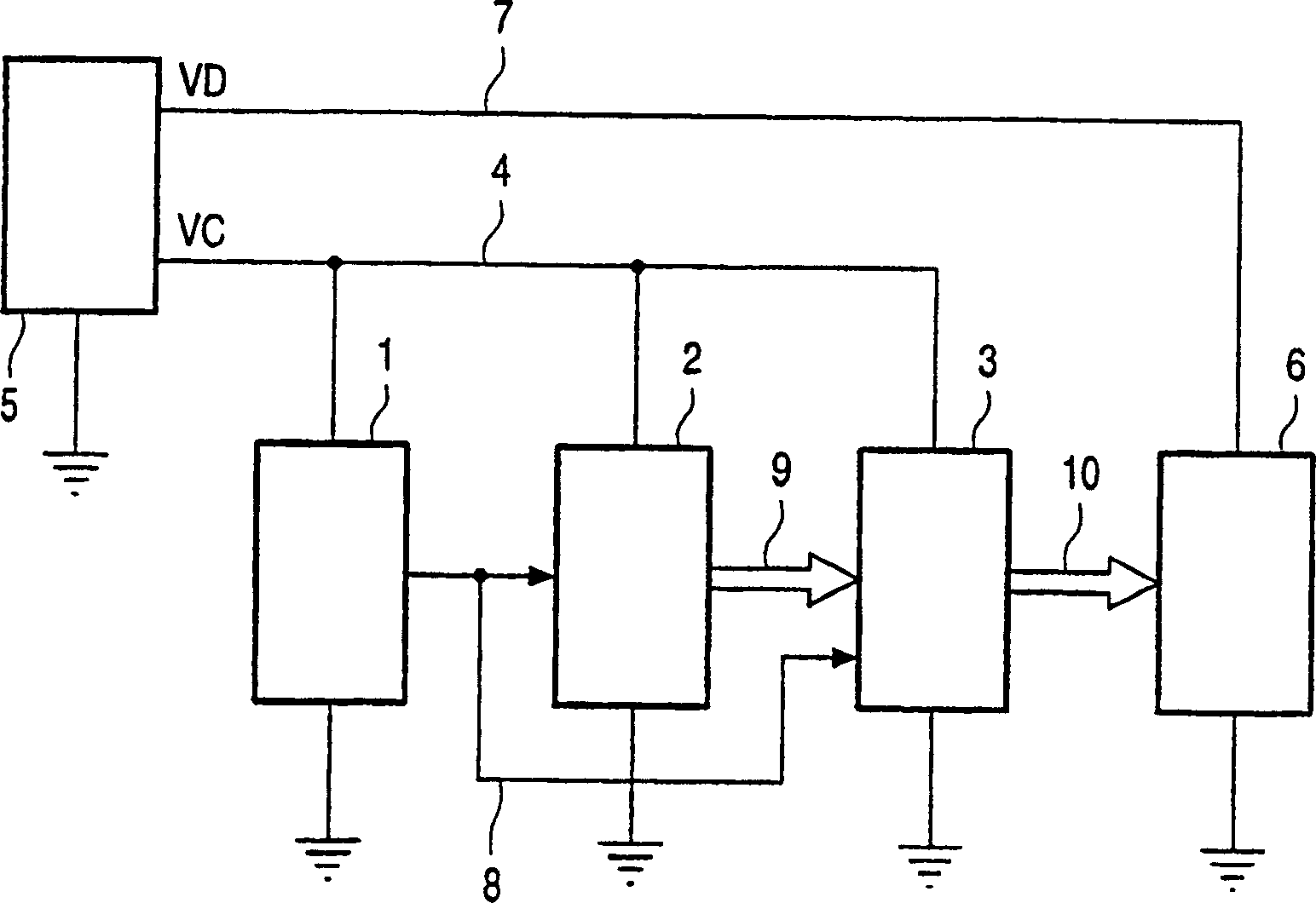
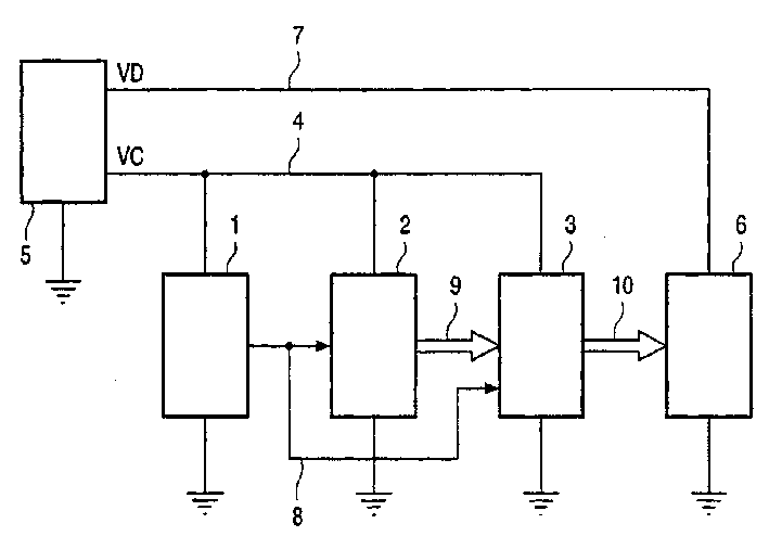
[0025] figure 1 A block diagram of a part of a display device with a reflective LCD panel according to the invention is given.

[0026] Please see figure 1 , the operation detection circuit 1, the digital circuit 2 as the first circuit and the analog circuit 3 as the second circuit are connected to the power supply 5 through the power line 4, and a constant voltage VC is supplied thereto. The LCD panel (display unit) 6 is connected to the power supply 5 through the power supply line 7 to provide a constant voltage VD there. When the display device does not operate for more than a predetermined time, the operation detection circuit 1 provides a low-run sleep signal STBY to the digital circuit 2 and the analog circuit 3 through the signal line 8, and switches to the sleep mode.

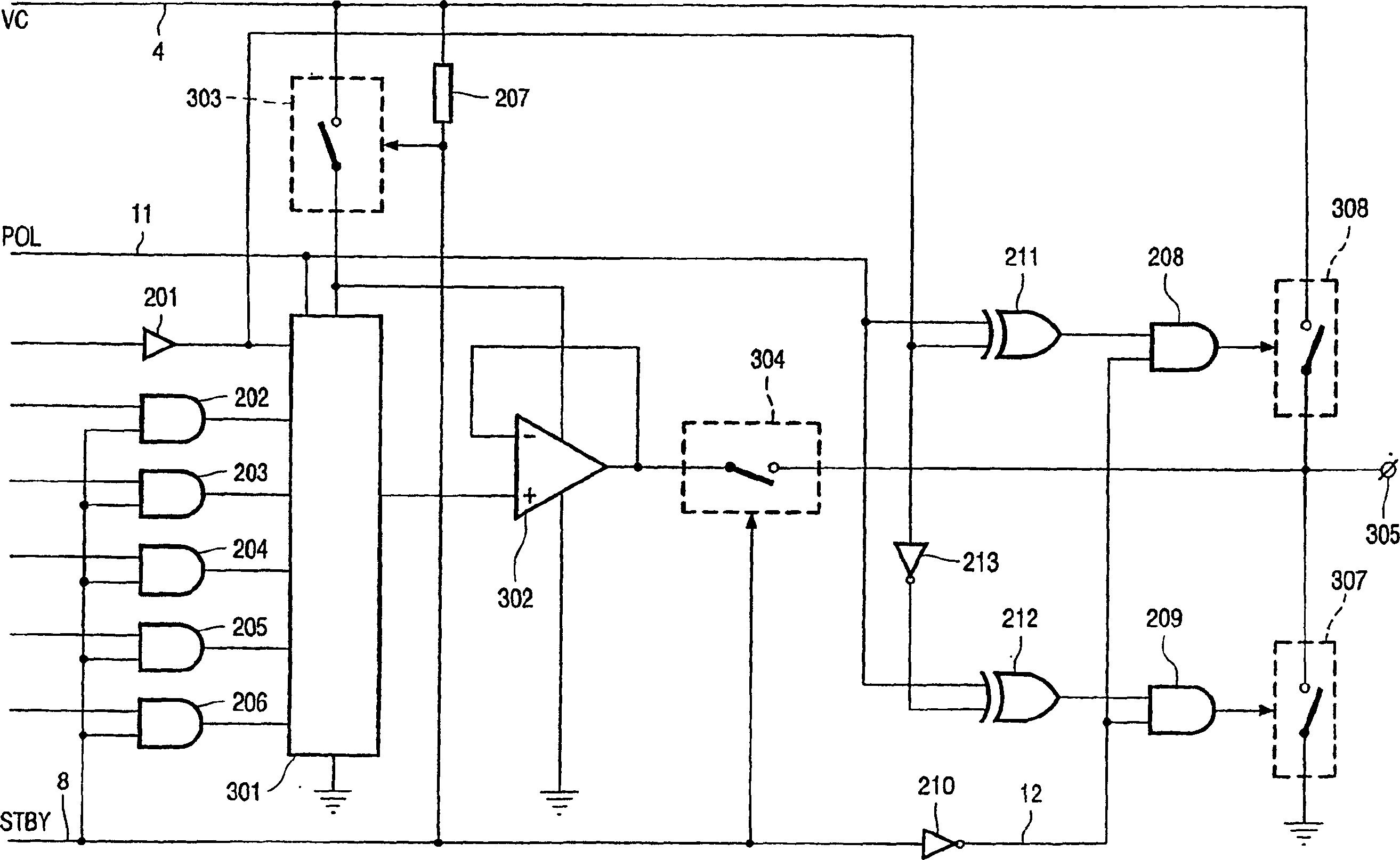
[0027] The digital circuit 2 is composed of a C-MOSIC that generates digital signals, and is used to generate display signals, and the signals are supplied to the analog circuit 3 through the signal l...


PUM


Abstract

The device has an LCD panel (6), a digital circuit 1 and an analog circuit (2) which generate display signals to be supplied to the LCD panel (6), and has functions of normal mode and stand-by mode in a status where electric power is supplied from a power source (5). In the normal mode, a multivalued display signal which can represent gradation levels is generated and supplied to the LCD panel (6), while in the stand-by mode, a binary display signal which does not represent gradation levels is generated and supplied to the LCD panel (6).

Description

technical field [0001] The present invention relates to display devices, and more particularly to display devices having liquid crystal display (LCD) panels. Background technique [0002] In display devices with a transmissive LCD panel, a backlight system is used to illuminate the displayed image from behind the LCD panel. In transmissive LCD panels used in notebook personal computers and PDAs (handheld digital devices), if the keyboard, mouse or similar operating device is not operated after a certain Sleep mode (sleep mode) of the displayed signal reduces power consumption. Especially since the power consumption of the backlight is large, the effect of switching to the sleep mode on the power reduction is significant. [0003] Disclosed in CN1195158A is a liquid crystal display (LCD) system used in battery-powered electronic equipment with a controller equipped with an LCD panel comprising an icon display LCD section and a dot matrix LCD section electrically insulated f...

Claims


Application Information

Patent Timeline
IPC IPC(8): G02F1/133G09G3/20G09G3/36
CPCG09G2330/022G09G2340/0428G09G3/3688G09G3/36
Inventor T·卡米雅M·亚穗
Owner TPO HONG KONG HLDG
Learn More