Signal processing method and device for laser range finding

A technology of laser ranging and signal processing, which is applied in measuring devices, electromagnetic wave re-radiation, radio wave measurement systems, etc., can solve the problems of large storage space, high cost, and increased manufacturing cost

Inactive Publication Date: 2005-01-05
SINTAI OPTICAL SHENZHEN CO LTD
View PDF5 Cites 0 Cited by
  • Summary
  • Abstract
  • Description
  • Claims
  • Application Information

AI Technical Summary

Problems solved by technology

[0007] 1. During the sampling process, each reference point of the sampling must be recorded. Therefore, for the same distance measurement interval, the higher the sampling period, the larger the memory capacity must be set, and increasing the number of sampling times will also occupy a larger storage space, so A memory with a larger capacity is required, which also increases the manufacturing cost;
[0008] 2. To increase the sampling cycle and sampling times, higher-speed components must be used, which cost more and consume more power

Method used


Image

  • Signal processing method and device for laser range finding
  • Signal processing method and device for laser range finding
  • Signal processing method and device for laser range finding

Examples


Embodiment Construction

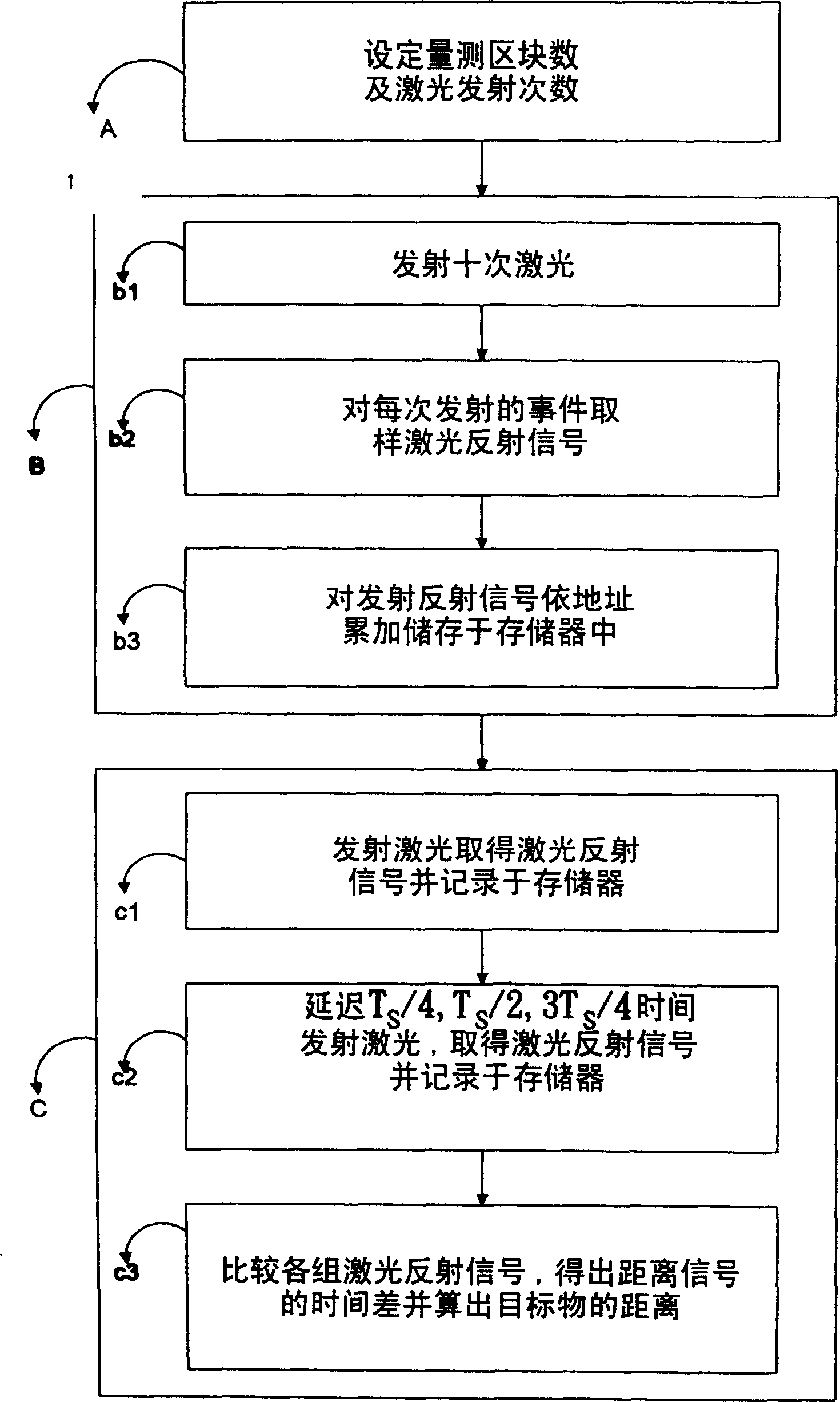
[0043] see Figure 1 to Figure 6 , a signal processing method for laser ranging provided by a preferred embodiment of the present invention, comprising the following steps:

[0044] A. Set the number of measurement blocks and the number of laser shots:

[0045] The total sampling time T of laser ranging T It is divided into four blocks, and each block is set to emit 10 times of laser light;

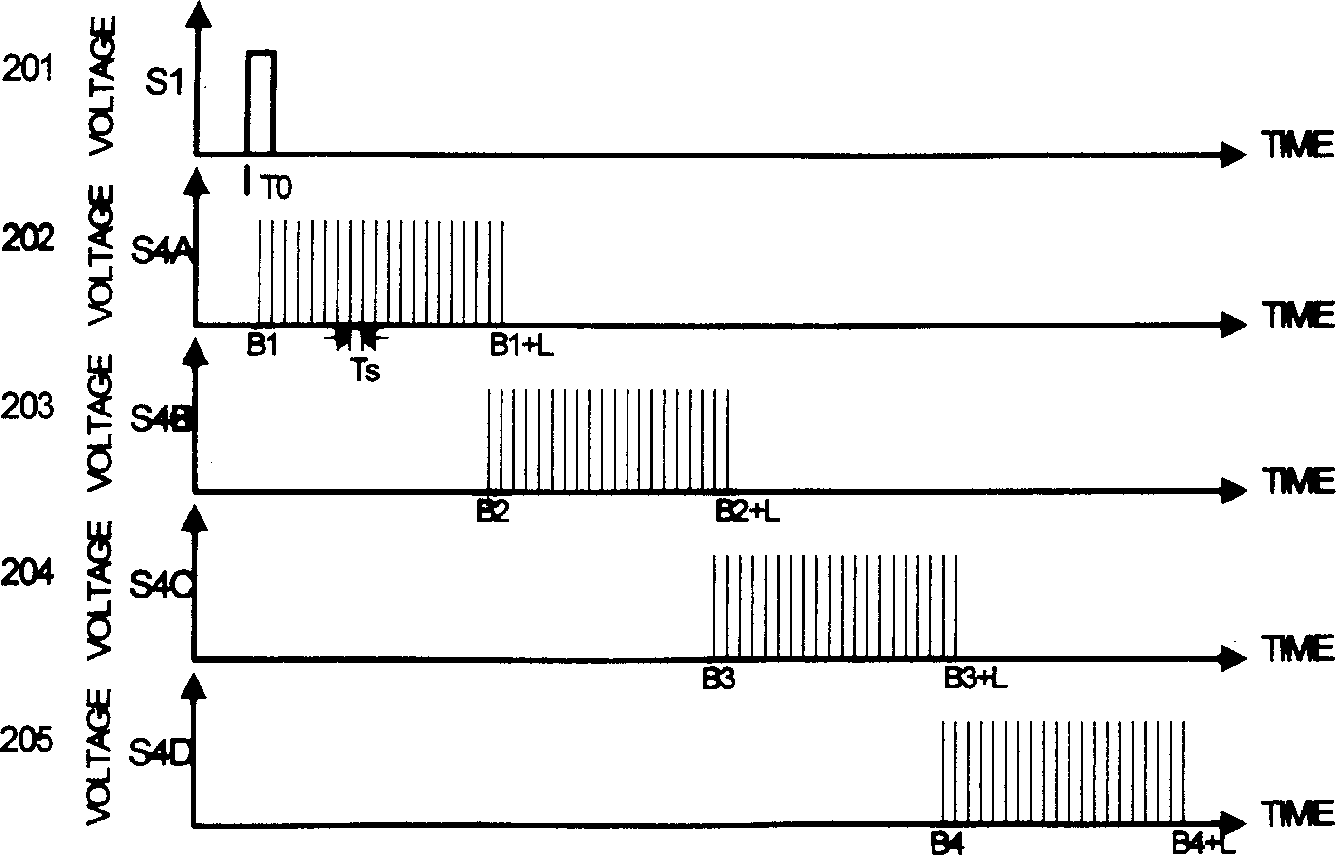
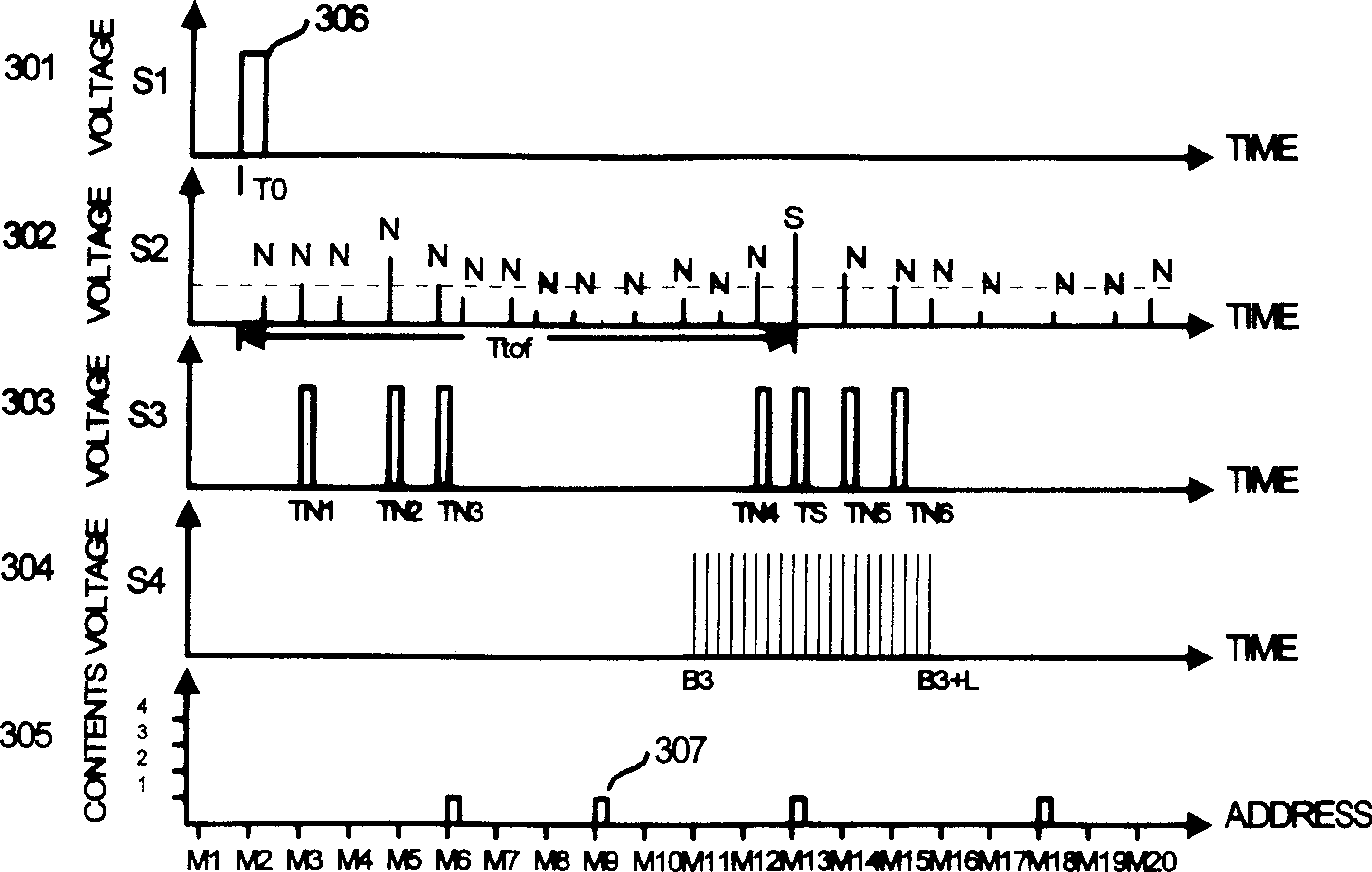
[0046] B. If figure 2 As shown, starting from the first measurement block, the laser reflection signal is sampled and counted sequentially in each block, so as to find out which block the target is located in. The following are the detailed steps in each block:

[0047] b1. Use the laser transmitter to emit 10 times of laser light:

[0048] b2. In each emission event, with a sampling period T s The method of continuous sampling is used to obtain the laser reflection signal, where the laser reflection signal may be the laser signal reflected by the target object, or it may be noise; ...


PUM


Abstract

The signal processing process for laser range finding includes the following steps: setting measured block number and laser emitting number; sampling and counting the reflected laser signal beginning from the first block so as to find the block the target is in; emitting laser beam with preset delay time in the block the target is in and sampling and operating on the reflected laser signal so as to find the precise distance between the laser range finder and the target.

Description

technical field [0001] The present invention is related to a laser range finder, and in particular provides a signal processing method and device for a laser range finder, which effectively improves the accuracy of the laser range finder without increasing the sampling period and sampling times. And save the memory required by the laser range finder. Background technique [0002] Laser range finder (Laser Range Finde) is one of the important devices for measuring distance. The conventional laser range finder uses a pulse (pulse) type laser transmitter to emit a laser pulse (laser pulse) of about 10ns-20ns onto a target. The laser signal reflected by the target is received by a laser receiver, and the distance is calculated by the following formula (1): [0003] T d =2L / C………………………………………(1) [0004] Formula (1) where L represents the distance between the laser range finder and the target, C represents the speed of light, and T d Represents the delay time between the emitt...

Claims


Application Information

Patent Timeline
Patent Type & Authority Patents(China)
IPC IPC(8): G01S7/483G01S17/10
Inventor 赖以仁简碧尧黄瑞峰洪志伟
Owner SINTAI OPTICAL SHENZHEN CO LTD
Why Eureka
Try Eureka