Optical guide unit, its manufacturing method , and dental appliances having optical guide unit

A technology of light guide and light source, used in dentistry, dental drilling, light guide of lighting devices, etc., can solve the problems of easy breaking and damage of glass fibers

Inactive Publication Date: 2005-02-02
NAKANISHI INC
View PDF0 Cites 0 Cited by
  • Summary
  • Abstract
  • Description
  • Claims
  • Application Information

AI Technical Summary

Problems solved by technology

On the one hand, the middle section 35 enables the light guide unit 30 to deform freely to fit the inner shape of the channel, but on the other hand, the free glass fibers in this section 35 are easily broken and damaged, which causes operational problems

Method used


Image

  • Optical guide unit, its manufacturing method , and dental appliances having optical guide unit
  • Optical guide unit, its manufacturing method , and dental appliances having optical guide unit
  • Optical guide unit, its manufacturing method , and dental appliances having optical guide unit

Examples


Embodiment Construction

[0030] Now, the present invention will be described in detail with reference to a preferred embodiment with reference to the accompanying drawings, but the present invention should not be limited to this embodiment.

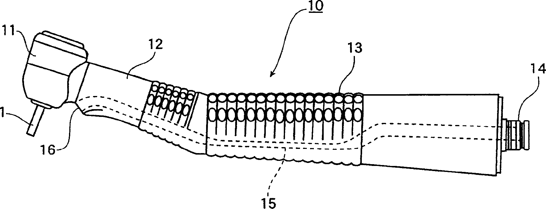
[0031] figure 1 A side view of one embodiment of a dental hand instrument 10 of the present invention is shown. The instrument 10 includes a head 11 for detachably holding a dental treatment tool 1, a neck 12 extending directly from the head 11, a neck 12 extending at an angle for the operator to grasp The gripping portion 13 and a connecting portion 14 disposed at the proximal end of the gripping portion 13 and used for connecting with a coupler (not shown). The coupler accommodates a light source (not shown) and connects the hand instrument 10 to a dental unit (not shown) or dental hose (not shown) in a conventional manner.

[0032] The hand instrument 10 is provided with a channel 15 extending generally axially from the connecting portion 14 and terminating ...


PUM


Abstract

There is disclosed a light guide unit including a bunch of glass fibers capable of transmitting light from a light source to a desired site, a sheath of a thermocontracting resin contracted to cover the bunch of glass fibers for substantially its overall length, and a filler of a hardening resin hardened to fill spaces between the glass fibers within the sheath. Also disclosed are a method for producing the light guide unit, and a dental handpiece having the light guide unit.

Description

technical field [0001] The present invention relates to a light guide unit suitable for installation in an instrument, such as a dental handpiece, for delivering light from a light source to a desired location, and to a light guide unit for the manufacture of such a light guide Unit method and a dental hand instrument in which the light guide unit is installed. Background technique [0002] In many medical or industrial instruments, there is an illumination system for illuminating a desired position, which includes a light source and a light guide unit installed in an instrument for transmitting light from the light source to a desired position. Location. [0003] For example, in a typical dental hand instrument with a coupler, a light source, such as a halogen lamp, is disposed within the coupler, and a light guide unit is accommodated in a passage through the hand instrument for the Light is delivered from the light source to the head or neck of the manual instrument. T...

Claims


Application Information

Patent Timeline
IPC IPC(8): A61B1/07A61B19/00A61C1/08B29C43/12B29C43/18B29L31/10
CPCA61B1/07A61B1/24A61C1/088A61B2019/5206A61B2090/306F21V2200/10
Inventor 中西崇介
Owner NAKANISHI INC
Why Eureka
Try Eureka