Gas turbine and its combustion chamber.

A combustor and turbine technology, applied in the field of combustors, can solve problems such as difficult access to combustors, insufficient air volume, etc.

Inactive Publication Date: 2005-02-02
MITSUBISHI HEAVY IND LTD
View PDF0 Cites 1 Cited by
  • Summary
  • Abstract
  • Description
  • Claims
  • Application Information

AI Technical Summary

Problems solved by technology

However, in the general combustor 1 and the gas turbine using the conventional combustor 1, since a large amount of air is used for combustion, the amount of air necessary to cool the walls of the combustor 1 is insufficient.
Therefore, the problem arises that it is difficult to obtain a combustor that strikes a balance between sufficient combustion capability and cooling capability

Method used


Image

  • Gas turbine and its combustion chamber.
  • Gas turbine and its combustion chamber.
  • Gas turbine and its combustion chamber.

Examples


Embodiment Construction

[0038] Embodiments of the present invention will be described below with reference to the accompanying drawings.

[0039] first embodiment

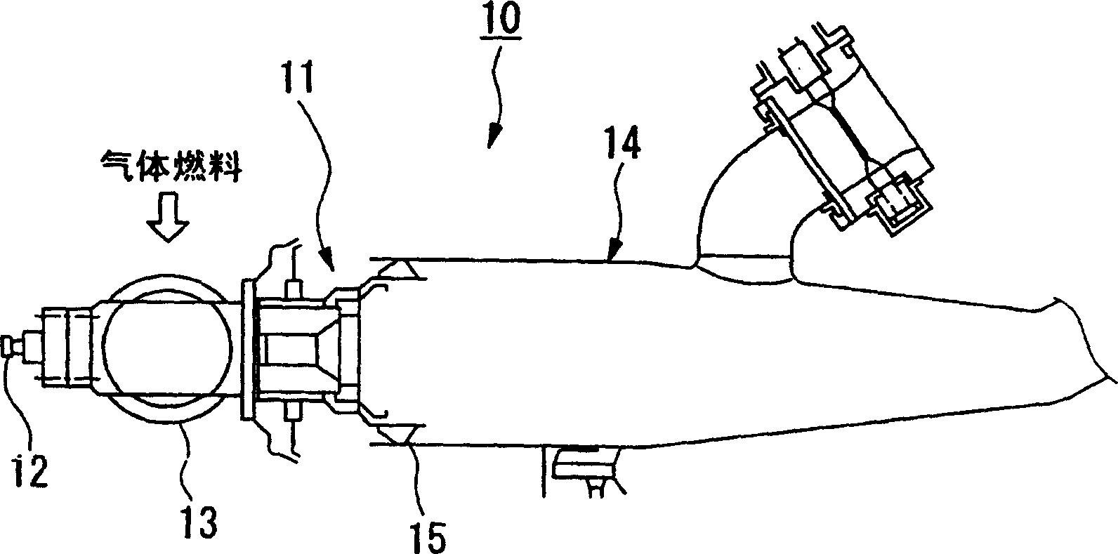
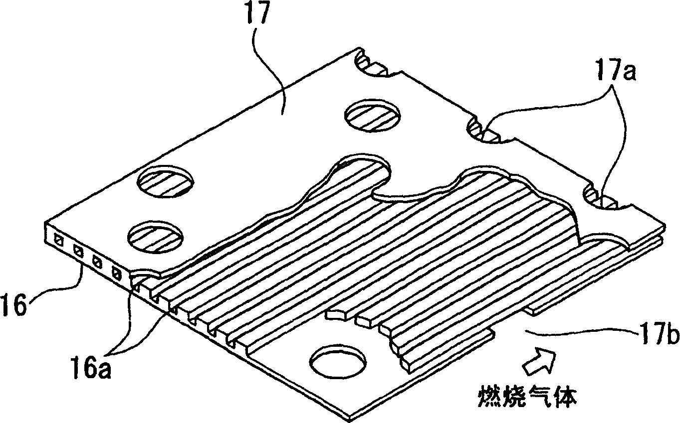
[0040] figure 1 and figure 2 It is the first aspect of the combustion chamber of the present invention. More precisely, figure 1 is a cross-sectional view of the combustion chamber. figure 2 An important part of the combustion chamber for cooling operation. figure 1 The illustrated combustor combusts fuel to produce combustion gases that drive a turbine (not shown). The combustion chamber 10 has a nozzle portion 11 .

[0041] A pilot nozzle 12 and a main nozzle 13 are contained in the nozzle section 11 . Air compressed by an air compressor (not shown in the figure) is supplied to the nozzle portion 11 to be mixed with fuel supplied from the pilot nozzle 12 . Here the mixture of air and fuel is ignited; thereby forming a pilot flame there.

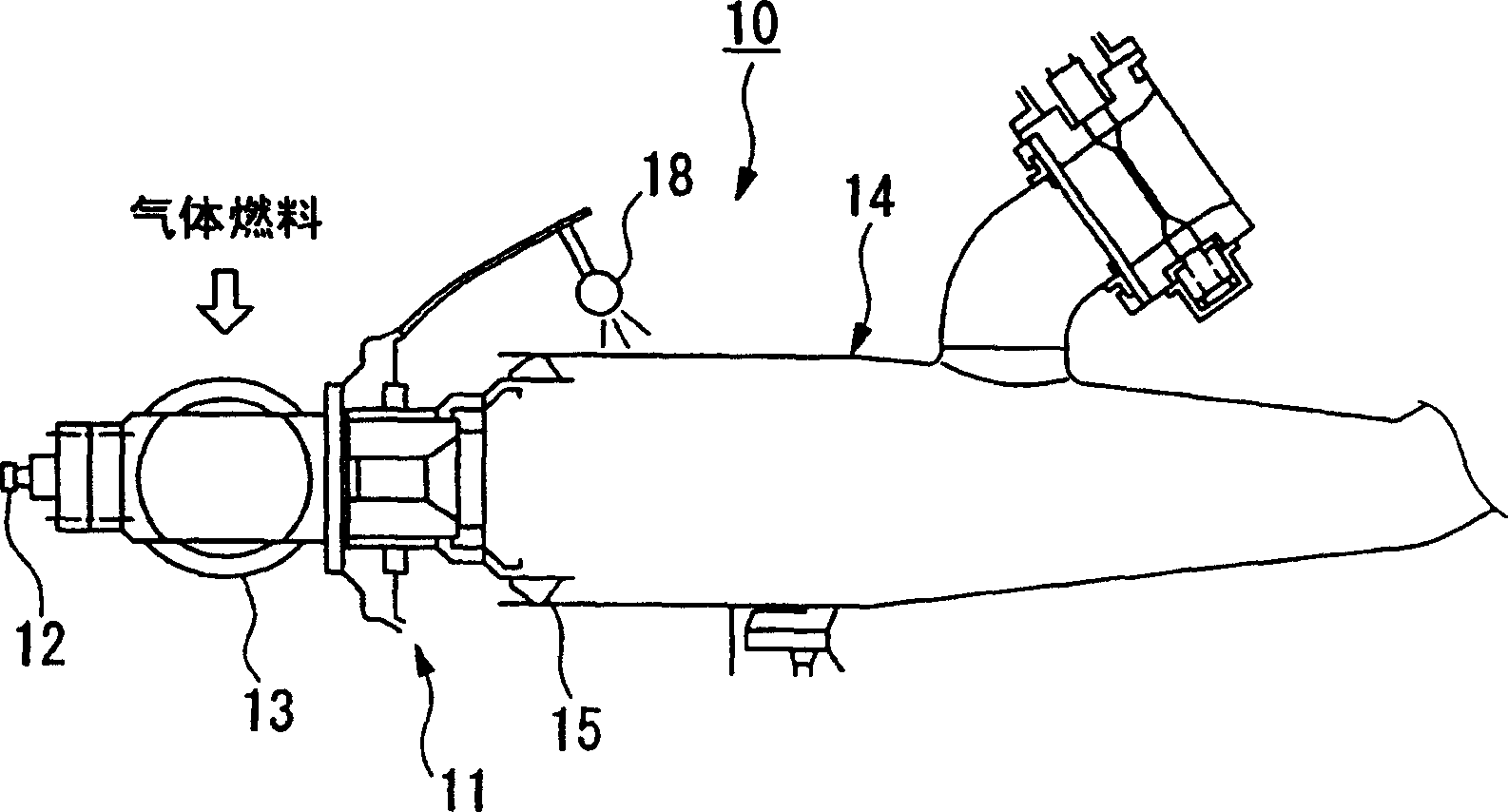
[0042]The main nozzle 13 injects fuel. Guide the flame to ignite the fuel. The igni...


PUM


Abstract

A combustor section (14) is disposed downstream of a nozzle section (11). The combustor section (14) extends from a downstream end of the nozzle section (11) to an entrance of a gas turbine and supplies a combustio n gas which is generated by combusting a premixed gas to a gas turbine. The combustor section (14) is formed by an inner tube and a tail tube unitarily. The combustor (10) is provided with a wall cooling apparatus for cooling a wall surface of the combustor (10). On the inner wall of the combustor section (14), grooves are formed. An entrance for introducing an air for cooling action is disposed on the outer wall of the combustor section (14). The introduced air performs a film cooling and connective cooling in a combined manner. By doing this, the temperature of the combustion gas may be high, and a highly efficient gas turbine is realized.

Description

technical field [0001] The present invention relates to a combustor capable of efficiently combusting a fuel having a low calorific value. The invention also relates to a gas turbine having a combustion chamber as described above. Background technique [0002] Figure 8 A typical combustion chamber is shown. A gas turbine burning low-calorie fuel is equipped with a combustor 1 . In the combustion chamber 1, when fuel is injected into the nozzle portion 2 through the main nozzle 3, the fuel ignited by the combustion chamber portion 4 is combusted to generate combustion gas. The combustion gases are supplied to a gas turbine (not shown in the figure) located downstream thereof. The combustor part 4 comprises an inner tube 5 connected to the nozzle part 2 and a tailpipe 6 connected to the inner tube. [0003] In the combustion chamber 1 described above, it is necessary to cool the walls of the combustion chamber portion 4 . This cooling operation uses compressed air that h...

Claims


Application Information

Patent Timeline
Patent Type & Authority Patents(China)
IPC IPC(8): F02C7/18F23M5/08F23R3/00
CPCF23R2900/03042F23M5/085F23R3/005F23R3/002F23R2900/00002
Inventor 万代重实太田将丰田中克则西田幸一
Owner MITSUBISHI HEAVY IND LTD
Why Eureka
Try Eureka