
Base station receiver and transmitter radio frequency front end

A technology of base station transceiver and radio frequency front-end, applied in the field of base station transceiver radio frequency front-end, can solve the problems of inconvenience, dispersion, inconvenience of centralized monitoring and management, etc., and achieve the effect of compact structure and small transmission loss

Inactive Publication Date: 2005-03-23
HUAWEI TECH CO LTD
View PDF0 Cites 0 Cited by
  • Summary
  • Abstract
  • Description
  • Claims
  • Application Information

AI Technical Summary

Problems solved by technology

[0009] 1. The system requires a lot of modules, which are distributed in multiple slots of the cabinet;
[0010] 2. The working status monitoring circuits of each functional module are distributed in each individual functional module, which is relatively scattered and inconvenient for centralized monitoring and management;
[0011] 3. There are many frames that need to install various functional modules, which is inconvenient to use

Method used


Image

  • Base station receiver and transmitter radio frequency front end
  • Base station receiver and transmitter radio frequency front end
  • Base station receiver and transmitter radio frequency front end

Examples


Embodiment Construction

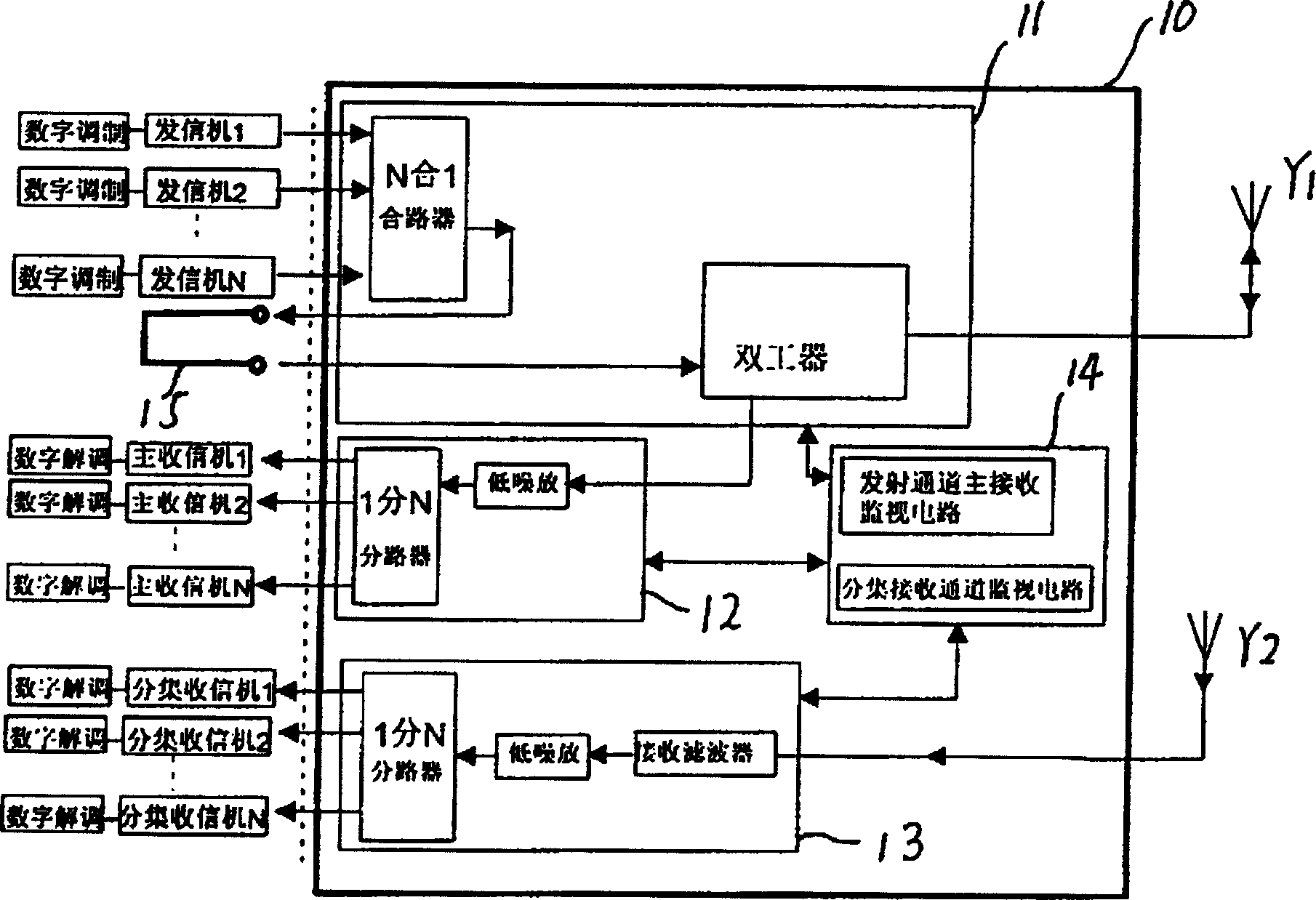
[0024] see Figure 5 As shown, the radio frequency front end 10 of the base transceiver station of the present invention includes a signaling unit 11 , a main receiving unit 12 , a diversity receiving unit 13 , and a monitoring unit 14 . The signaling unit 11, the main receiving unit 12, the diversity receiving unit 13, and the monitoring unit 14 are integrated into one module.

[0025] Described signaling unit 11 contains a transmitting combiner and a transmitting and receiving duplexer. In the transmitting unit 11, the input of the transmitting combiner is connected with the transmitter of the base station system, and the output of the transmitting combiner is connected to The transmitting and receiving duplexer is connected to the main antenna Y1 of the base station system.

[0026] The main receiving unit 12 contains a low noise amplifier and a main receiving splitter. In the main receiving unit 12, the input of the low noise amplifier is connected with the duplexer of the...


PUM


Abstract

This invention discloses a RF front end of base station sender / receiver including sending unit, master receiving unit, diversity receiving unit, monitor unit integrated in a module enabling the front end of the base station not only to keep original functions but also even tighten the structure to integrated in a main frame and emitting combined channel unit connected with a emitting / receiving duplexer by an external coaxial cable which can connect the emitting unit directly to the duplexer when it is not in combined channel.

Description

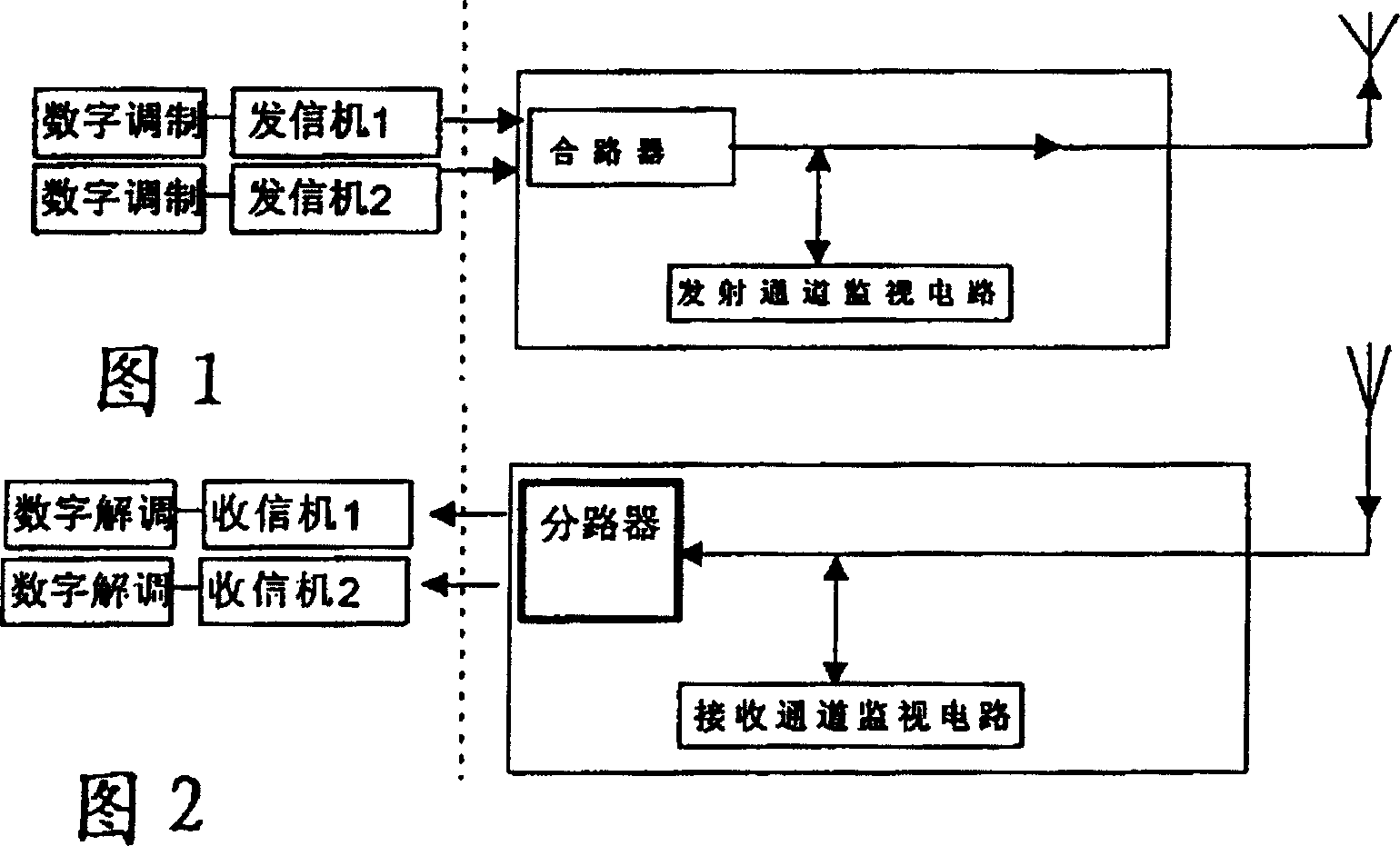
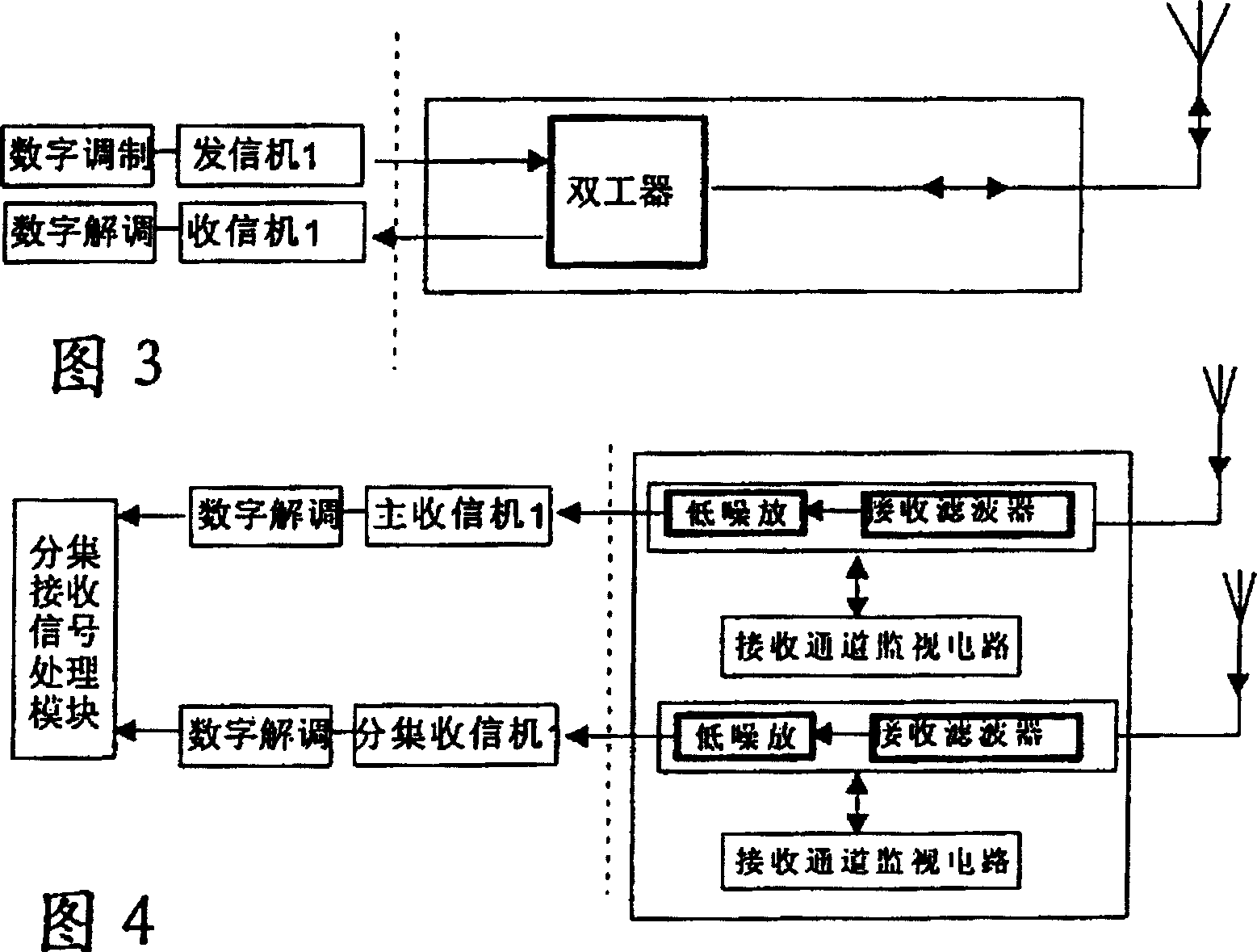
technical field [0001] The invention relates to a mobile communication system, more specifically to a radio frequency front end of a base transceiver station. Background technique [0002] In the wireless communication system, in order to improve the utilization rate of the outdoor antenna and feeder system, the front-end of the transceiver system often adopts multi-channel synthesis for the transmission signal, that is, the transmission combination technology, and at the same time, the monitoring circuit is added to monitor the transmission channel; For the received signal, low noise amplification (LNA) is often required, and at the same time, the amplified signal is divided into multiple channels, that is, the receiving branch technology, and the monitoring circuit is added in order to monitor the transmission channel; sometimes in order to solve the transmission signal and The limitations of using different antennas for receiving signals, using the combination technology ...

Claims


Application Information

Patent Timeline
Patent Type & Authority Patents(China)
IPC IPC(8): H04B1/40H04B1/50H04B7/08
Inventor 贺国秋李玉林艾鸣
Owner HUAWEI TECH CO LTD
Learn More