Calibration method of electric charge coupler response linearity

A charge-coupled device and calibration method technology, which is applied in electrical components, semiconductor/solid-state device testing/measurement, television, etc., can solve problems such as off-axis aberration affecting spot quality, high requirements for optical wedge coating, and affecting calibration accuracy, etc. , to achieve the effect of easy engineering realization, easy debugging, and uniformity

Inactive Publication Date: 2005-05-04
INST OF OPTICS & ELECTRONICS - CHINESE ACAD OF SCI
View PDF0 Cites 0 Cited by
  • Summary
  • Abstract
  • Description
  • Claims
  • Application Information

AI Technical Summary

Problems solved by technology

The disadvantage of this method is that the processing and coating requirements of the optical wedge are high, the optical path is not easy to adjust,

Method used


Image

  • Calibration method of electric charge coupler response linearity
  • Calibration method of electric charge coupler response linearity
  • Calibration method of electric charge coupler response linearity

Examples


Embodiment Construction

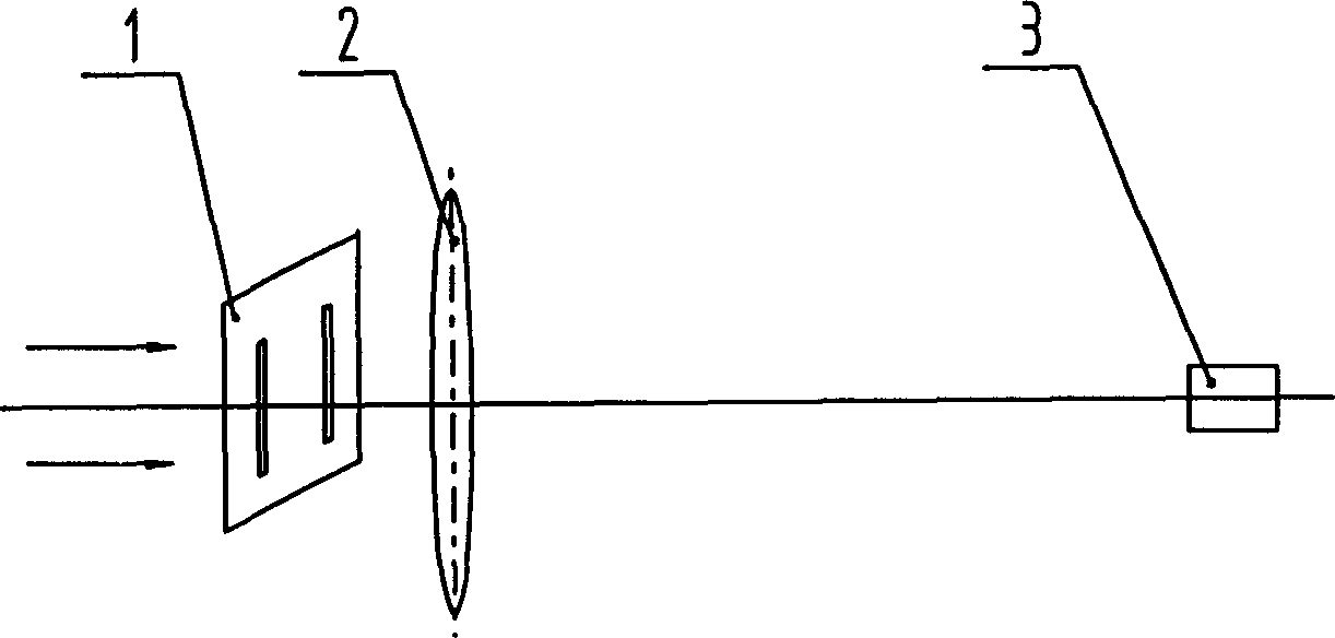
[0019] The present invention will be further described below in conjunction with the accompanying drawings and embodiments (selection of a double-slit diffraction screen). The embodiment of the present invention comprises the following steps: as figure 1 As shown, the embodiment of the present invention utilizes a beam of monochromatic plane light to irradiate the double-slit diffraction screen 1 . The monochromatic plane light converges to the rear focal plane of the Fourier lens 2 through the double-slit diffraction screen 1 and the Fourier lens 2 . The charge-coupled device 3 to be measured is placed on the back focal plane of the Fourier lens 2 so that the target surface of the charge-coupled device 3 coincides with the back focal plane of the Fourier lens 2 .

[0020] The following parameters are selected: the focal length of the Fourier lens 2 is f=1200 mm, the target surface of the charge-coupled device 3 to be measured is 3.2×2.4 mm, and the wavelength λ of the incide...


PUM


Abstract

The invention discloses a calibration method for response linearity of a charge coupled device. The present invention utilizes the monochromatic plane light to irradiate the diffraction screen, and converges it through the Fourier lens, uses a charge-coupled device to sample the light spot lattice of the back focal plane of the Fourier lens, and obtains the output gray value of the light spot lattice; the analysis is based on the Fraunhofer diffraction theory The calculated theoretical distribution value of the spot intensity and the output gray value sampled by the charge-coupled device realize the calibration of the response linearity of the charge-coupled device. The method has the characteristics of easy debugging and low cost, and is convenient for engineering realization.

Description

technical field [0001] The invention relates to a method for calibrating the response linearity of a charge-coupled device, in particular to a method for calibrating the response linearity of a charge-coupled device by measuring the response curve of the input light intensity and the output gray value of the charge-coupled device. Background technique [0002] Charge-coupled device is a new photoelectric conversion device, which can detect the change of its input light intensity according to its gray scale output change, and usually use its characteristic to detect the controlled object. However, due to the non-linearity of the response of the charge-coupled device and the response difference between the pixels of the charge-coupled device, it is necessary to calibrate the response linearity of the charge-coupled device. At present, there are mainly attenuation method and split-beam method for calibrating the response linearity of charge-coupled d...

Claims


Application Information

Patent Timeline
IPC IPC(8): G01J3/18G01N21/00H01L21/66H04N17/00
Inventor 段海峰杨泽平王淑青张雨东
Owner INST OF OPTICS & ELECTRONICS - CHINESE ACAD OF SCI
Why Eureka
Try Eureka