Device used for changing objective lens of microscope

A technology of microscopes and objective lenses, applied in microscopes, optics, instruments, etc., can solve problems such as inability to drive by motors, and achieve the effect of avoiding collisions

Inactive Publication Date: 2005-05-11
莱卡微系统及显微股份有限公司 +1
View PDF0 Cites 0 Cited by
  • Summary
  • Abstract
  • Description
  • Claims
  • Application Information

AI Technical Summary

Problems solved by technology

And it only changes between the two objective lenses, and it cannot be easily driven by a motor

Method used


Image

  • Device used for changing objective lens of microscope
  • Device used for changing objective lens of microscope
  • Device used for changing objective lens of microscope

Examples


Embodiment Construction

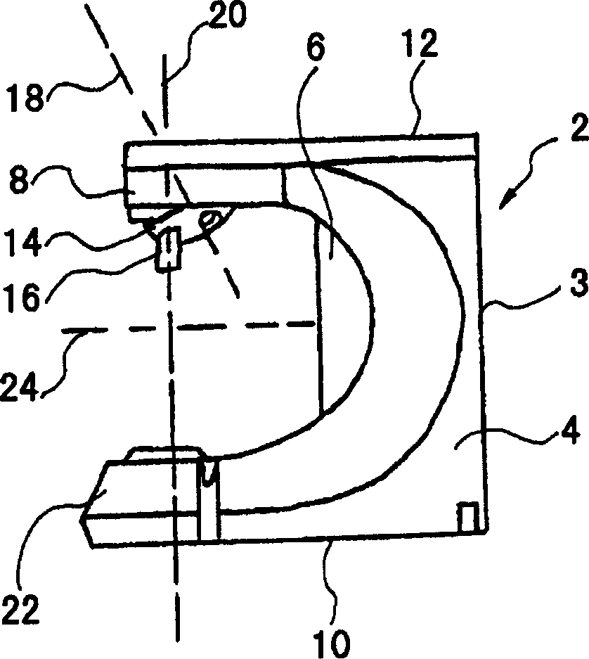
[0021] figure 1 Indicates a microscope according to the prior art. The microscope comprises a stand 2 defined by first and second side walls 4 and 6 and an end wall 8 . The first and second side walls 4 and 6 are also connected to each other by the rear wall 3 . The microscope also includes a base 10 and a head 12 . Installed in the head 12 is an objective turret 14, which supports several objective lenses 16 that can be rotated or rotated to the working position by the objective turret 14. The objective turret 14 rotates around a rotation axis. The objective 16 in the working position defines an optical axis 20 . An illumination device 22 for illuminating an object (not shown) lying on the stage plane 24 can be arranged, for example, on the base 10 of the microscope. The axis of rotation 18 and the optical axis 20 are arranged apart such that the plane defined by them is parallel to the first or second side wall 4 or 6 of the microscope.

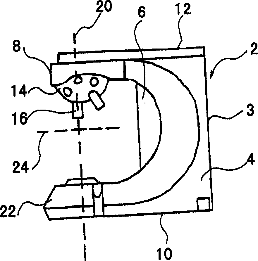
[0022] figure 2 Designating ...


PUM


Abstract

The invention describes a device for changing the objective lens in a microscope mainly used with a microscope platform having a so-called fixed platform structure. The inventive structure of the objective turret in the pedestal ensures that any damage to the manipulator or the object to be examined is excluded during the objective changeover. This is primarily achieved by the fact that the axis of rotation defined by the objective turret is arranged obliquely with respect to the first and second side walls of the microscope. It is further ensured that the object to be inspected is within the field of view after the objective lens is changed. The transformation of the whole objective lens as well as the setting of the magnification and the requirement of focusing are fully automatic and motor-driven.

Description

technical field [0001] The invention relates to a device for changing the objective lens in a microscope. In particular, it relates to a microscope objective lens changing device used in combination with a platform and a fixed platform. Background technique [0002] Vertical microscopes are often used when examining sections of biopsy since observation and measurements must be made from above. A plurality of manipulators with needles and capillaries are arranged in the object region and thus approach the object. A microscope with a fixed platform is usually used for this purpose, and the moving objective lens is used for focusing. Since the manipulator cannot move the stage, the objective must be moved. Such microscopes are generally characterized by their dense structure. For example, an objective lens and at least one manipulator point to an object point. This use also requires a special objective lens with an elongated structure at the top so that it can approach the...

Claims


Application Information

Patent Timeline
Patent Type & Authority Patents(China)
IPC IPC(8): G02B21/00G02B21/24G02B21/32G02B21/02
CPCG02B21/248
Inventor M·甘瑟尔M·吉尔伯特
Owner 莱卡微系统及显微股份有限公司
Why Eureka
Try Eureka