Multi-blank multi-layer co-extruding blow moulding machine

A co-extrusion and blow molding machine technology, applied in the field of plastic machinery, can solve problems affecting blowing quality, work performance, and high labor costs

Inactive Publication Date: 2009-10-21
浙江东方州强塑模实业有限公司
View PDF0 Cites 13 Cited by
  • Summary
  • Abstract
  • Description
  • Claims
  • Application Information

AI Technical Summary

Problems solved by technology

However, the existing extrusion blow molding machines have the following defects: First, in order to increase the strength, chemical resistance and barrier resistance of the product, it is usually made of two or three layers of different plastic materials, that is, two or three screws Extrude different molten plastics separately, two or three kinds of molten plastics enter the die, and extrude one layer after another. However, the existing three-layer extrusion blow molding machine is a single die, and only one can be extruded at a time. , the work efficiency is low; second, the existing extrusion blow molding machine is a single station, that is, there is only one blow molding system, and its production efficiency is low; third, since the extrusion blow molding machine is a one-step molding machine, when the dough passes through After the die is extruded,...

Method used


Image

  • Multi-blank multi-layer co-extruding blow moulding machine
  • Multi-blank multi-layer co-extruding blow moulding machine
  • Multi-blank multi-layer co-extruding blow moulding machine

Examples


Embodiment Construction

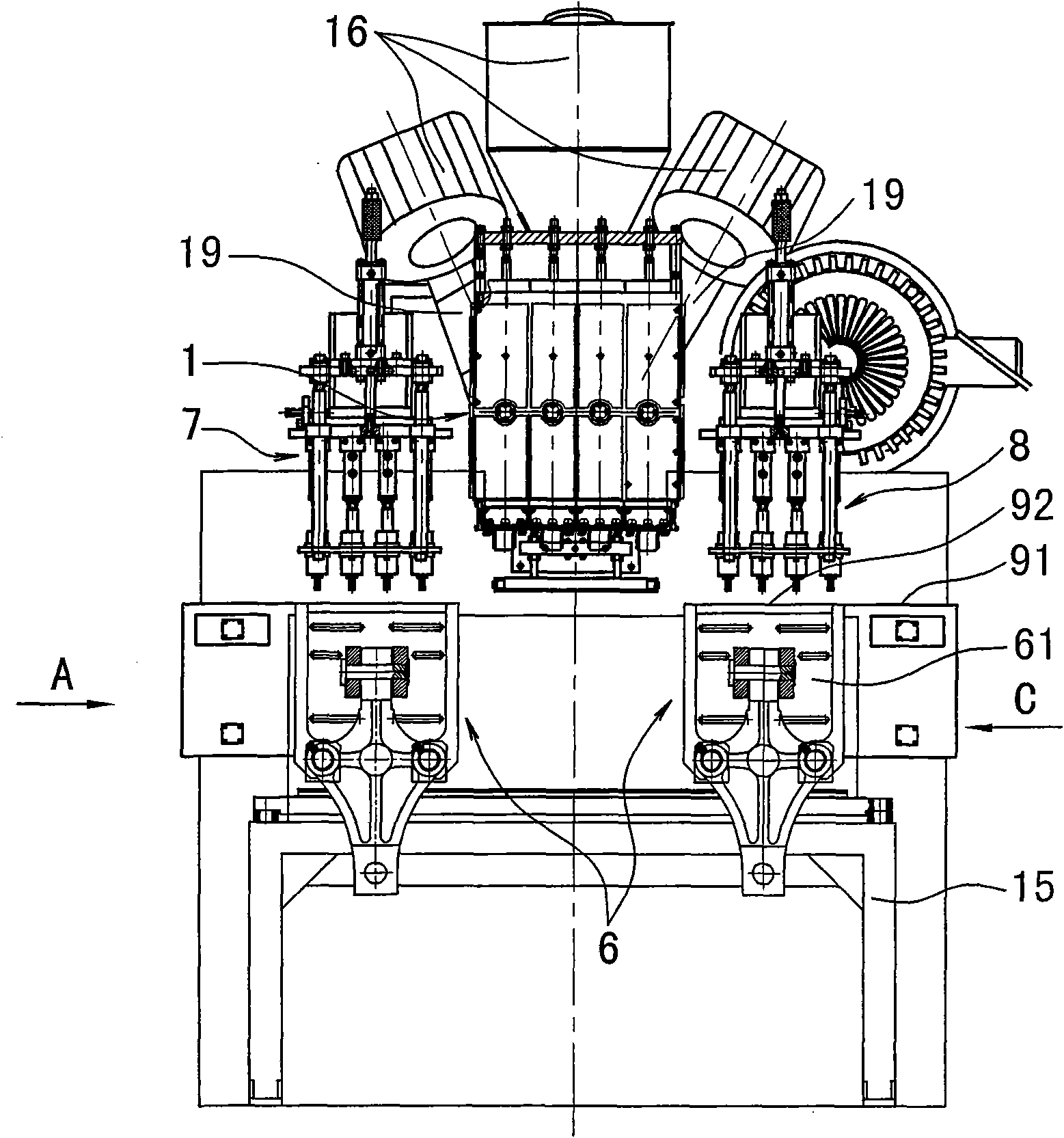
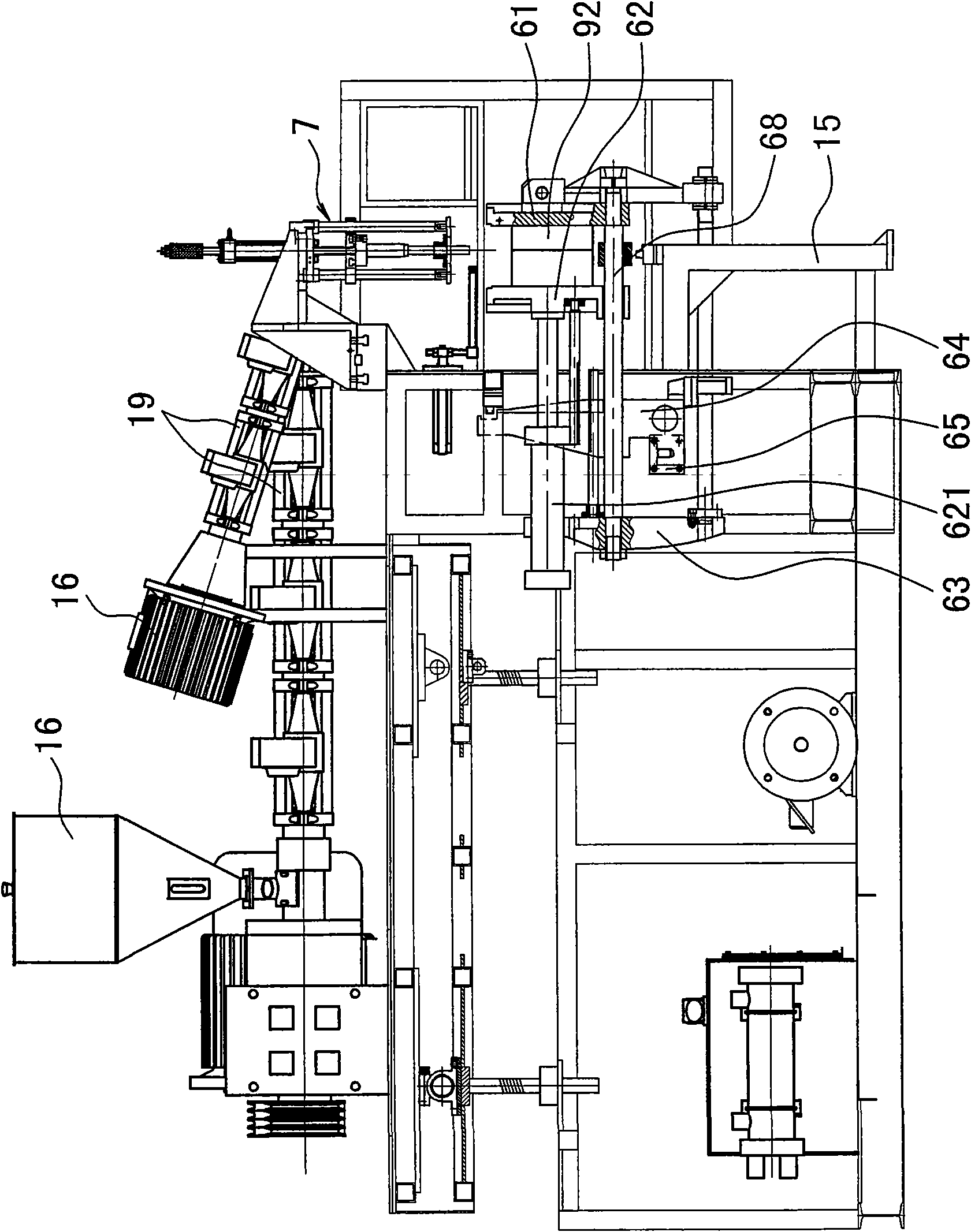
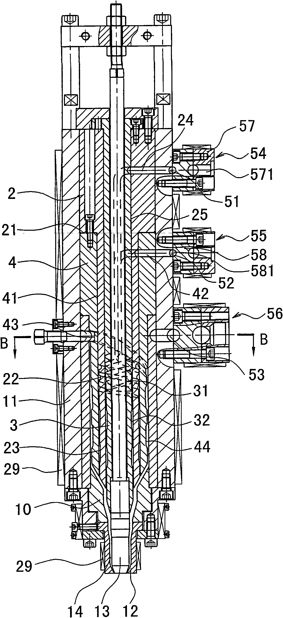
[0019] The invention discloses a multi-preform multilayer co-extrusion blow molding machine, such as figure 1 , figure 2 As shown, it includes a plasticizing system, a die extrusion system, and a blow molding system. The plasticizing system includes a hopper 16, a barrel 19, a screw in the barrel, and an electric heating device on the barrel; the mold The head extrusion system includes more than one die head, each die head is made with a feed port connected to a screw, the die head includes a die head body 11, the lower end of the die head body 11 is connected to a die 12, and the center of the die 12 is provided with a core die 13 The gap between the core mold 13 and the die 12 forms an annular extrusion port 14; there are two blow molding systems, each of which includes a blowing mechanism and a mold opening and closing mechanism. The mold opening and closing mechanism includes a guide rod 68. The front template 61, the middle template 62 and the rear template 63 are connected...


PUM


Abstract

A multi-blank multi-layer co-extruding blow moulding machine comprises a plasticizing system, a mold head extruding system and a blow moulding system. The mold head extruding system comprises more than one mold head, each mold head is provided with a feeding port connected with a screw rod; the mold head comprises a mold head main body connected with a mouth mold which is provided with a core mold; the core mold and mouth mold form an extruding port, wherein a guide body A and a guide body C are mounted in the mouth mold main body; the guide body A is provided with a step; a small head under the step is sleeved in a middle hole C of the guide body C; the small head is provided with a guide groove A and a vertical flow passage A; a big head is provided with a transverse flow passage A; a guide body B is arranged in the guide body A; the guide body B is provided with a guide flow passage B and a vertical flow passage B; the guide flow groove B is communicated with the feeding port; the guide body C is provided with the transverse flow passage C; the transverse flow passage C is connected with the guide flow groove A and the feeding port B; the guide body C is provided with a guide flow groove C and a vertical flow passage C, the guide flow groove C is communicated with the feeding port C; the vertical flow passage A, the vertical flow passage B and the vertical flow passage C are jointed at the external wall of core mold and communicated with the extruding port.

Description

Technical field [0001] The invention relates to an extrusion blow molding machine for plastic hollow containers, in particular to a multi-parison multilayer co-extrusion blow molding machine, and belongs to the field of plastic machinery. Background technique [0002] Extrusion blow hollow plastic molding machine is the main equipment for molding hollow containers (such as mineral water bottles, beverage bottles, medicine bottles, cosmetic bottles, etc.), including plasticization system, die extrusion system and blow molding system, the plasticization system Including a barrel, the barrel is connected with a screw; the die extrusion system includes more than one die, each die is made with a feed port connected to more than one screw, the die includes a die main body, a die main body The lower end is connected to the die, and the center of the die is provided with a core die. The gap between the core die and the die forms an annular extrusion port; the blow molding system includes...

Claims


Application Information

Patent Timeline
IPC IPC(8): B29C69/00B29C47/06B29C49/32B29C49/48B29C49/50B29C49/58
Inventor 施金亨王自强
Owner 浙江东方州强塑模实业有限公司
Why Eureka
Try Eureka