Microwave oven

A technology of microwave ovens and microwaves, which is applied in the field of microwave ovens and can solve problems such as complex structures of microwave ovens and impossibility of microwaves

Inactive Publication Date: 2005-05-25
DAEWOO ELECTRONICS CO LTD
View PDF0 Cites 0 Cited by
  • Summary
  • Abstract
  • Description
  • Claims
  • Application Information

AI Technical Summary

Problems solved by technology

[0006] In such a microwave oven, since the movement of electrons is controlled by the resultant force of the electric field and the magnetic field, a large number of magnets are required, which complicates the structure of the microwave oven. Moreover, since the microwave generating device adopted in the conventional microwave oven is a bipolar type, the It is impossible to control the output of the microwave

Method used


Image

  • Microwave oven
  • Microwave oven
  • Microwave oven

Examples


Embodiment Construction

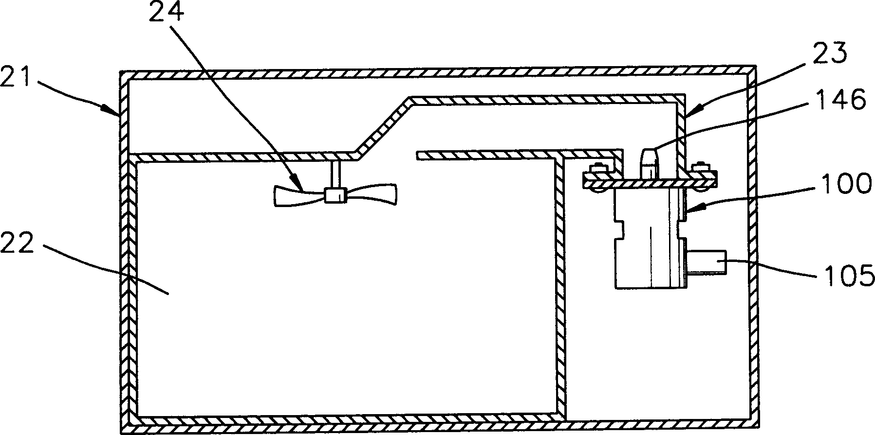
[0021] refer to image 3 A microwave oven according to the present invention includes a housing 21, a device 100 for generating microwaves, a power supply device 105 mounted on the device 100, and a cooking chamber 22 for containing food. Microwave generating device 100 comprises a filter box 101, its bottom is covered by a plate 102, and its top is covered by a bracket 103 (see Figure 4 ).

[0022] refer to Figure 4 with 5 , the filter box 101 has a heater 110, the heater is used as a heating element, and is electrically connected with the power supply device 105, the cathode 120, the first grid 130, the second grid 140 and the anode 150. Moreover, the inside of the filter box 101 is kept vacuum.

[0023] The heater 110 is composed of a filament, and the cathode 120 is located on the heater 110. When the heater is heated, the disk-shaped cathode 120 emits thermal electrons, which are used to control and bundle the electrons emitted from the cathode 120. The first grid ...


PUM


Abstract

A microwave oven includes a microwave generating device having a cathode and a first grid. The first grid has holes to convert electrons from the cathode into electron beams, and a metal film to reduce the emission of secondary electrons from the first grid. The microwave generating device also includes a resistor for generating an offset voltage on the first grid, a second grid with holes, an anode for receiving electrons passing through the holes of the second grid, and a A drive voltage source that provides drive voltages to the cathode and anode. There are multiple protrusions on the anode to reduce the emission of secondary electrons from the anode.

Description

technical field [0001] The present invention relates to a microwave oven, in particular to a microwave oven equipped with a structurally simple device for generating microwaves. Background technique [0002] figure 1 Shown is a microwave oven, which includes a housing 1, a power supply unit 2 with a high-voltage converter (not shown) and a high-voltage capacitor (not shown), a cylindrical magnetron 10 for generating microwaves, and a Cooking chamber 3 for food. Such as figure 2 As shown, the magnetron is a cylindrical bipolar vacuum tube, and typically includes a cathode 11 disposed in its center, a pair of magnets 12a, 12b respectively located above and below it, a magnetron disposed around the cathode 11 An anode 13 and an antenna 14 associated with the anode 13. [0003] When the power supply device 2 applies an operating voltage of, for example, 4KV to the input terminal 15 , the cathode 11 is heated and emits electrons, and the emitted electrons are received by the...

Claims


Application Information

Patent Timeline
Patent Type & Authority Patents(China)
IPC IPC(8): H05B6/66H01J23/06H01J23/075H01J25/04H05B6/72
CPCH01J23/06H01J25/04H05B6/72
Inventor 郑利教
Owner DAEWOO ELECTRONICS CO LTD
Why Eureka
Try Eureka