Fluidized bed reactor gases distributing plate

A fluidized bed reactor and gas distribution plate technology, applied in chemical instruments and methods, chemical/physical processes, etc., can solve problems such as dead holes, limited range of action, and influence on reaction yield, and achieve enhanced anti-deposition ability, Easy cleaning and modification, and increased operational stability

Inactive Publication Date: 2005-06-22
CHINA PETROLEUM & CHEM CORP +1
View PDF0 Cites 2 Cited by
  • Summary
  • Abstract
  • Description
  • Claims
  • Application Information

AI Technical Summary

Problems solved by technology

[0008] 1) Due to the fixed gas volume, the horizontal injection port of the hood is too large, resulting in insufficient injection gas velocity, and the range of action of each hood on the distribution plate is limited, which makes it difficult to ensure that large particles do not deposit on the plate, and the anti-deposition ability is not good. strong
[0009] 2) The hood structure of the distribution plate in the prior art is not stable enough in operation, and dead holes and dead zones often occur
[0010] 3) The structure of the distribution plate in the prior art cannot form a layer of gas film on the surface of the distribution plate, and cannot allow the fluidized material to react in the gas film, which affects the improvement of the reaction yield
[0011] 4) The arrangement of the air caps of the distribution plate in the prior art cannot completely eliminate the occurrence of dead zones, which also affects the anti-deposition ability of the distribution plate and affects the improvement of the reaction yield
[0012] 5) The distribution plate in the prior art cannot resist being blocked by active substances for a long time, thus affecting the production cycle of the device

Method used


Image

  • Fluidized bed reactor gases distributing plate
  • Fluidized bed reactor gases distributing plate
  • Fluidized bed reactor gases distributing plate

Examples


Embodiment

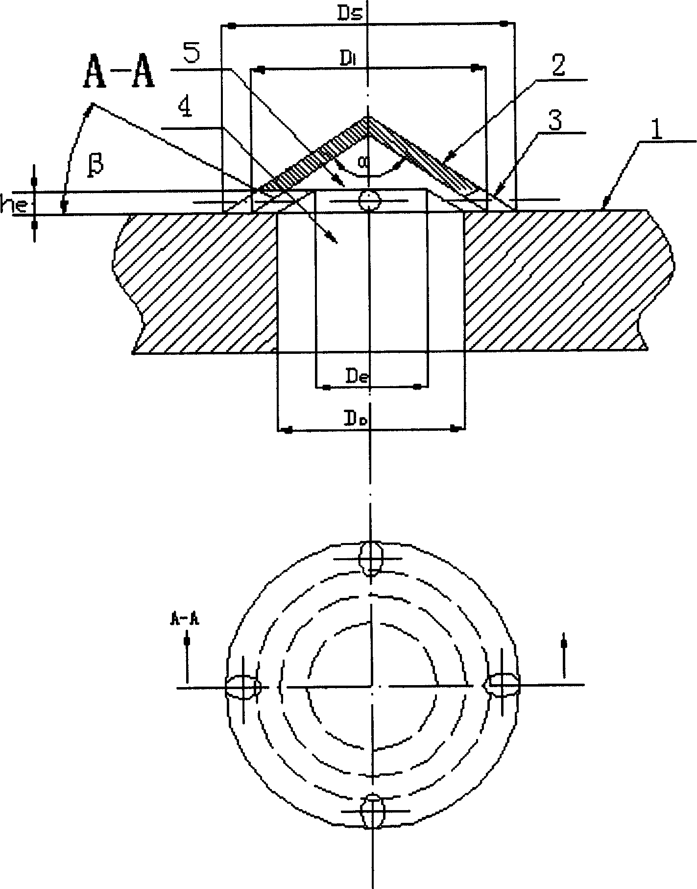
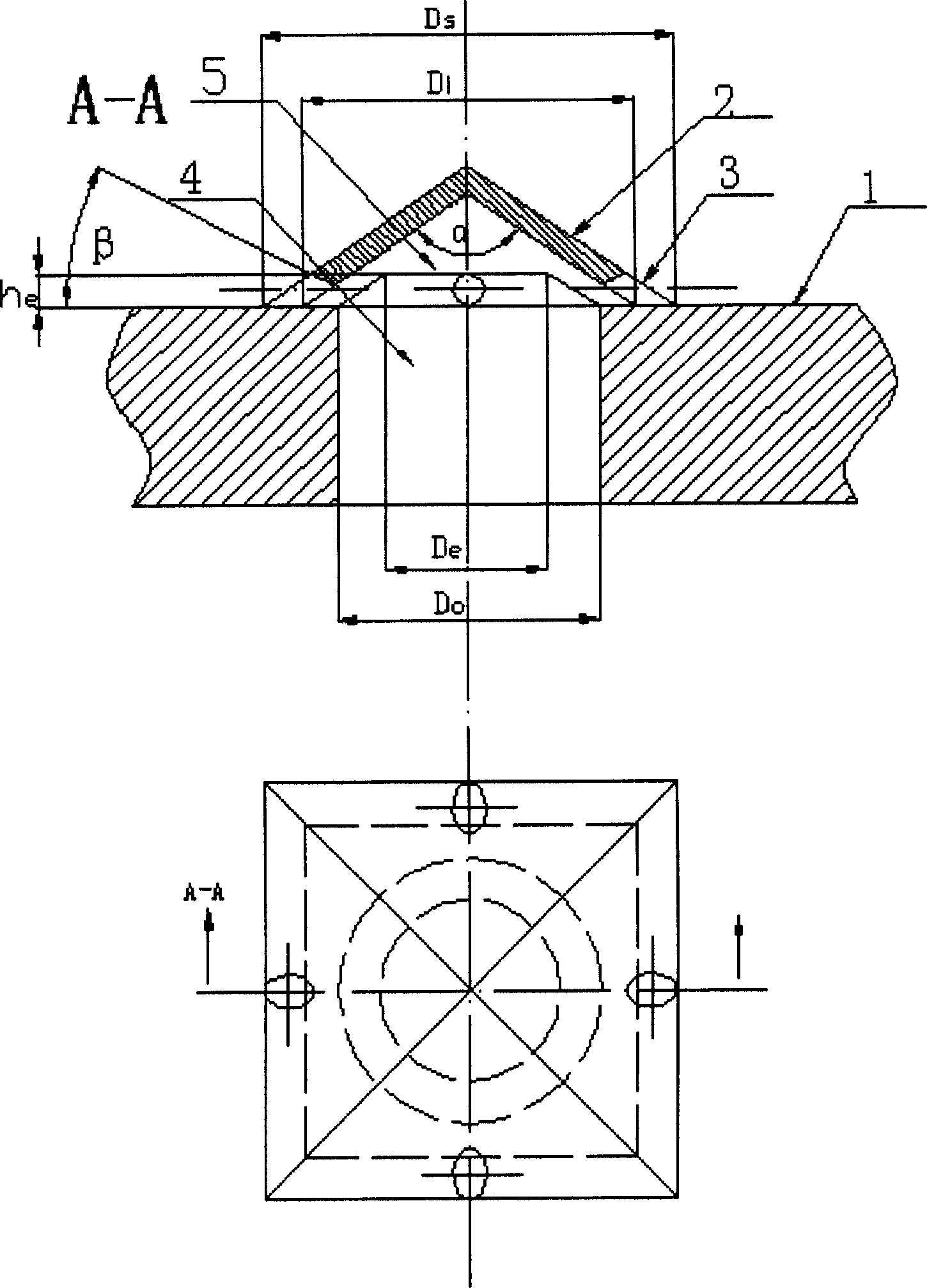
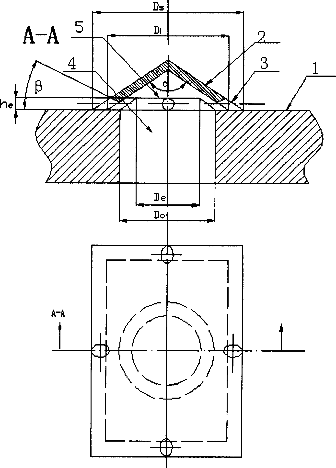
[0033] The Unipol fluidized bed olefin polymerization reactor imported from United Carbon is used, and the bottom installation is as follows figure 1 and the distributor plate of the present invention shown in 4. Operated in condensing mode, high density polyethylene is produced.

[0034] 1) Operating data of density polyethylene products

[0035] Reaction raw materials: ethylene, propylene, 1-butene, hydrogen

[0036] Liquid content in recycle stream: 9%~26%wt

[0037] Space-time yield: 134.8kgPE / m 3 *hr

[0038] 2) The case of continuous operation for 12 months:

[0039] The circulation flow rate is stable and there is no obvious fluctuation, which proves that the distribution plate is atomized evenly.

[0040] There is no increase in the pressure difference of the distribution plate, and it is always maintained at 2700-2970kg / m 3 Between, indicating that the distribution plate is not clogged.

[0041] The temperature of the four temperature detection points on the d...


PUM


Abstract

The invention discloses a gas distribution plate of a fluidized bed reactor. It has a gas distribution plate, with air inlet holes on the gas distribution plate, and a hood is welded on each air inlet hole of the gas distribution plate, and two or more circular and square injection holes are opened on the hood. Or a long jet slit, its size parameter is: the equivalent diameter D of the jet hole on the hood or the long jet slit i and distribution plate inlet hole diameter D 0 Ratio D i / D 0 =0.2~0.6, the angle β=0°~75° between the injection direction and the horizontal line, a circular, square or conical leak-proof weir is arranged at the inside of the wind cap and the upper end of the air inlet hole. Advantages of the present invention: 1) the The pressure drop on the distribution plate of the invention is transferred to the injection hole, ensuring that large particles are not deposited on the plate, and the anti-sedimentation ability is enhanced; 2) A layer of gas film is formed on the surface of the distribution plate of the fluidized bed, so that the entire bed material is lifted, thereby fully Fluidization; 3) The operation stability of the fluidized bed is increased, and the production cycle of the fluidized bed is improved; 4) The cleaning and modification of the wind cap are convenient, and the flexibility is enhanced.

Description

technical field [0001] The invention relates to a fluidized bed reactor, in particular to a gas distribution plate of a fluidized bed reactor. Background technique [0002] Distributor plates are an important part of industrial fluidized bed equipment. Although it has a direct effect range of only 0.2-0.3 meters on the entire fluidized bed, it has a decisive influence on the fluidized state quality of the entire fluidized bed and the operating performance of the reactor. Specifically, the functions of the fluidized bed distribution plate include: [0003] 1) Distribute the fluid evenly while minimizing the energy consumption of the fluid passing through the distribution plate. This can be achieved by adjusting the opening ratio of the distribution plate or the ratio of plate pressure drop to bed pressure drop, and selecting appropriate pre-distribution means. [0004] 2) Ensure that good gas-solid contact conditions are formed near the distributi...

Claims


Application Information

Patent Timeline
Patent Type & Authority Patents(China)
IPC IPC(8): B01J8/44
Inventor 阳永荣侯琳熙胡晓萍王靖岱陈纪忠吴文清
Owner CHINA PETROLEUM & CHEM CORP
Why Eureka
Try Eureka