Method of welding steel guide rails

A guide rail and arc welding technology, which is applied to the joints of rails, rails, welding equipment, etc., can solve the problems of complex equipment, high cost, and inability to provide this time

Inactive Publication Date: 2005-07-13
LINCOLN GLOBAL INC
View PDF8 Cites 1 Cited by
  • Summary
  • Abstract
  • Description
  • Claims
  • Application Information

AI Technical Summary

Problems solved by technology

Furthermore, these existing methods of joining spaced railroad rails by arc welding are expensive, require complex equipment, and require extensive time to prepare for the welding process and to complete the welding process on site
This time is not available in field welding of rails

Method used


Image

  • Method of welding steel guide rails
  • Method of welding steel guide rails
  • Method of welding steel guide rails

Examples


Embodiment Construction

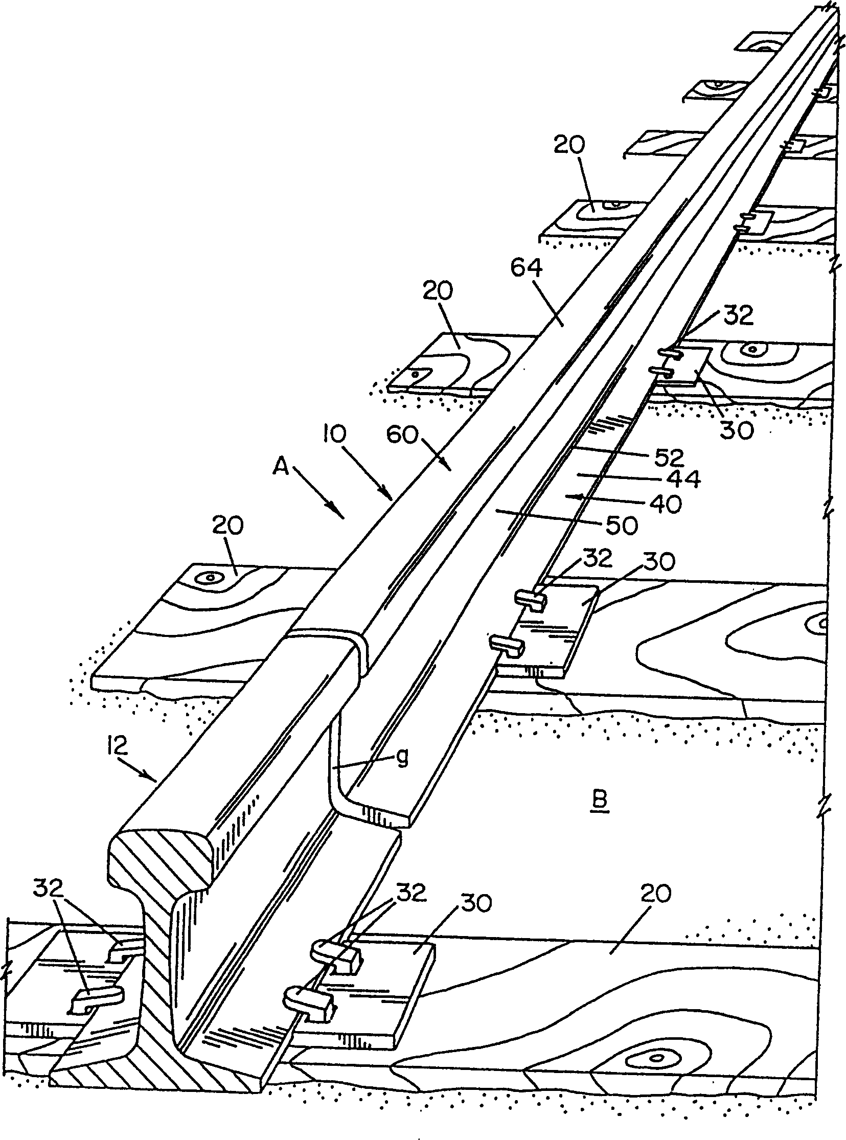
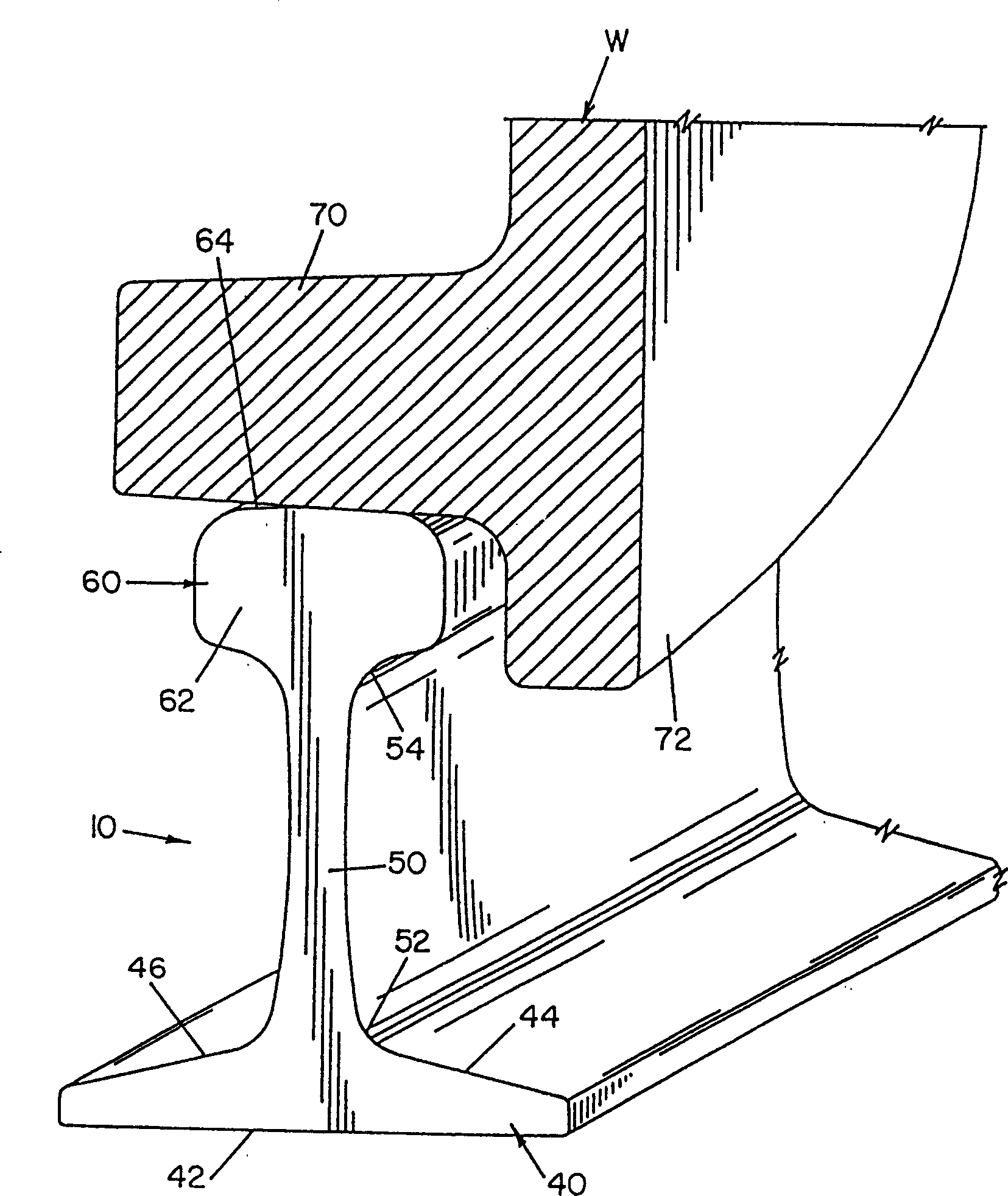
[0047] Referring now to the accompanying drawings, the purpose of which is to illustrate and not limit the preferred embodiment of the present invention, figure 1 A steel rail A lying on a rail bed B is shown, comprising rails 10 and 12 to be joined to form a continuous welded track. The guide rails 10 and 12 are supported on the rail bed B by sleepers 20, steel support covers 30 and channel nails 32, the rails being spaced longitudinally to form a gap g therebetween which is to be filled with molten weld metal so that the two rails are joined together in this The location is connected. The gap 9 may be the gap between two rail sections to be repaired, or the gap between two rail sections initially to be installed as a continuous welded rail system. If the gap g is for maintenance, it is often necessary to cut the rail and insert a long section of the rail. This method is used to repair broken rails, broken seams or damaged seams. In all examples, the two spacer rails 10 an...


PUM


Abstract

A method of gas shielded welding of steel rails, comprising the steps of providing elongated steel partitions in gaps at the bottom of the divided rails, formed by a gas shielded arc welding process with a filler metal electrode starting the arc between the electrode and the partitions The molten metal fills the gap above the partition. The root pass is placed using a spray arc welding process, the second layer is placed partly using a pulsed arc welding process and partly using a jet welding process, and the rest of the rail bottom gap and the gap between the rail web and rail head are placed using a pulsed arc process.

Description

technical field [0001] The present invention relates to a method and system for welding spaced ends of steel guide rails, and more particularly to a method and system for welding two spaced steel guide rails in the field by arc welding. Background technique [0002] The invention is illustrated and described herein in connection with the welding of steel guide rails, it being understood that the invention is also applicable to the welding of other types of rails, such as crane rails and other rails used to support wheeled vehicles or devices. [0003] The present invention improves the orbital welding method and system disclosed in my US5773779 and US5877468 patents and my application serial number 167463 on October 7, 1998, which is incorporated herein by reference. [0004] Over the years, a great deal of work has been put into joining the spacer steel rails using a variety of butt welding methods. These efforts have generally been costly and unsuccessful due to limitatio...

Claims


Application Information

Patent Timeline
Patent Type & Authority Patents(China)
IPC IPC(8): E01B11/50B23K9/02B23K9/035B23K9/038B23K9/095B23K9/12B23K9/173B23K101/26
CPCB23K9/0213B23K9/0216B23K9/035E01B29/42B23K2101/26
Inventor 米歇尔·J·莫洛克
Owner LINCOLN GLOBAL INC
Why Eureka
Try Eureka