
Miniature size measurer

A measuring device, a technology of micro-size, applied in measuring devices, using optical devices, semiconductor/solid-state device testing/measurement, etc., can solve problems such as inability to measure line widths correctly, and achieve the effect of avoiding operation errors

Inactive Publication Date: 2005-08-10
V TECH CO LTD
View PDF0 Cites 1 Cited by
  • Summary
  • Abstract
  • Description
  • Claims
  • Application Information

AI Technical Summary

Problems solved by technology

[0006] In other words, (1) There is a high possibility that the operator mistakenly selects the specified part, and therefore, it is possible to measure the line width of a part that is not the measurement target
(2) Even if the specified part is selected correctly, it is very likely that the measurement method that does not meet the specified part is selected, for example, the automatic focus is not in focus, and the automatic dimming does not meet the requirements. Dimensions such as line width may not be measured correctly

Method used


Image

  • Miniature size measurer
  • Miniature size measurer
  • Miniature size measurer

Examples


Embodiment Construction

[0017] Embodiment of the invention

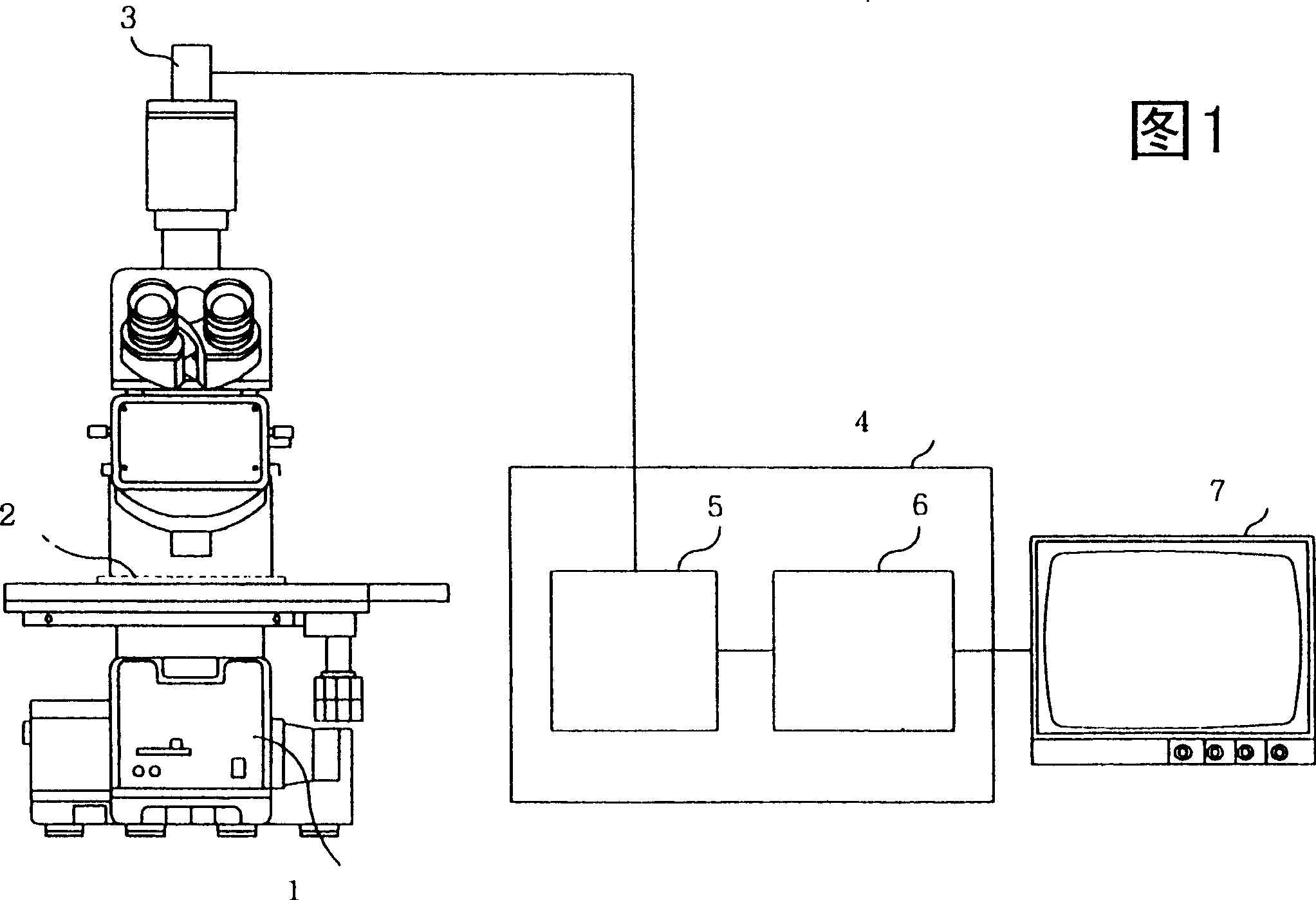
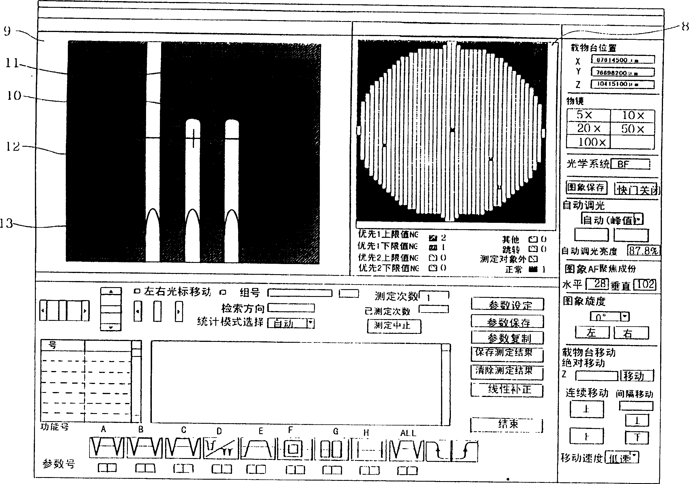
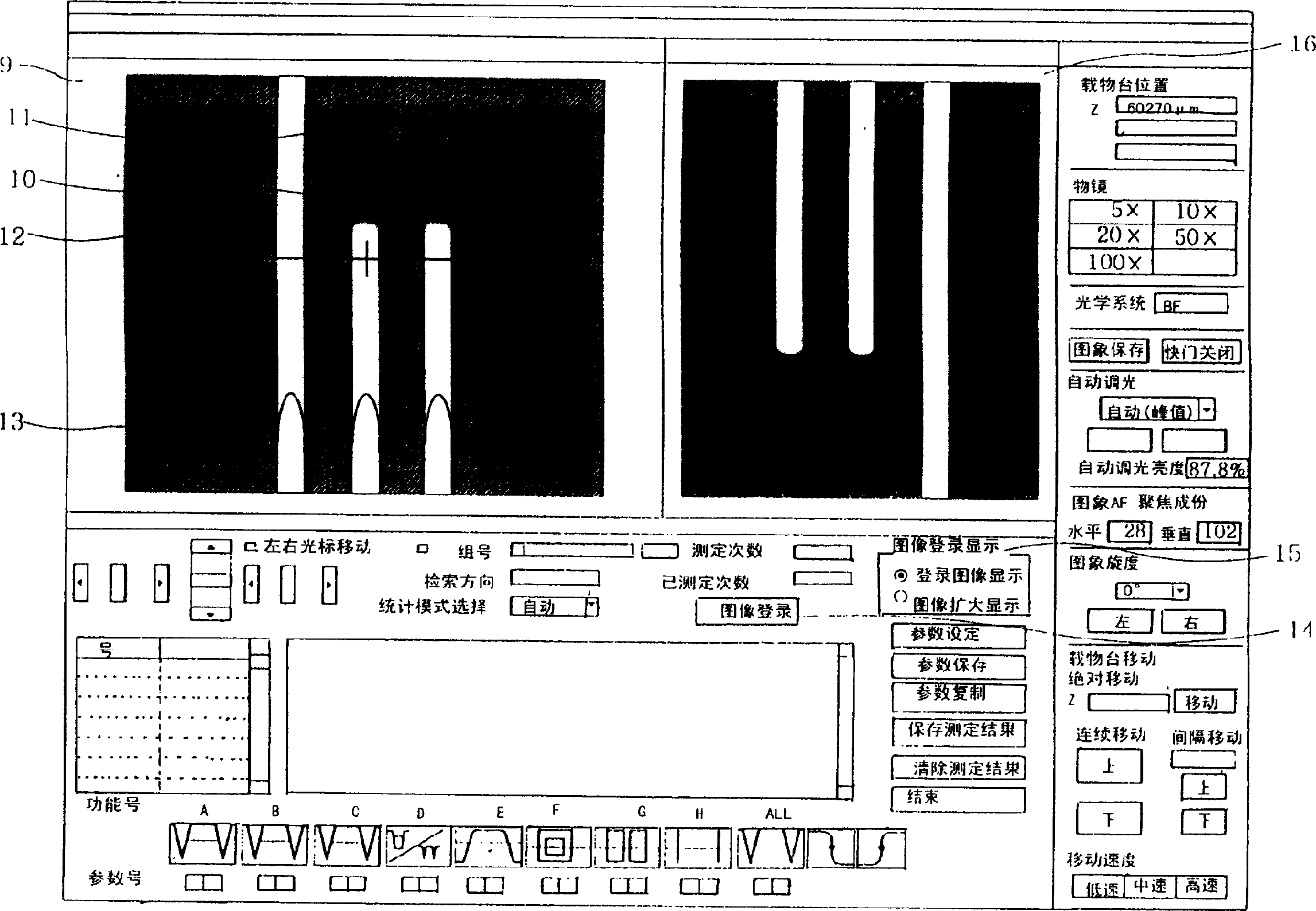
[0018] Embodiments of the present invention will be described in detail below using the drawings. Fig. 1 is a block diagram of a conventional micro-size measuring device. The configuration of the micro-size measuring device shown in this figure can also be used to realize the present invention. Here, in the block (group) structure of the micro-size measuring device shown in this figure, the action different from the action described in the prior art is: the selected one of the many measurement methods pre-recorded on the hard disk 6 The measurement target part of the measurement object corresponding to the method (レシピ) is captured as sample image information according to the combination of the measurement conditions of the measurement method (レシピ), and the corresponding relationship with the measurement method is marked and stored in the hard disk 6, at the same time, when the same object to be measured is measured again based on the reco...


PUM


Abstract

To stably accurately carry out the measuring work using a micro- dimension measuring device which measures the dimension of an object to be measured on the basis of image information outputted from an imaging device. An image information sample which is obtained by photographing the object to be measured using the measuring device in accordance with a measurement condition recorded beforehand, is stored in a memory device. When measuring the object to be measured in accordance with the recorded measurement condition, the image information sample corresponding thereto is displayed.

Description

technical field [0001] The present invention relates to a technique for improving the measurement efficiency of a micro-sized measuring device used for semiconductor wafers and semiconductor wafer processing masks, etc., Background technique [0002] A block configuration example of a conventional micro-size measuring device will be described with reference to FIG. 1 . In this figure, an enlarged image of a sample 2 obtained by an optical microscope 1 is photoelectrically converted into image signals by a television camera 3 which is an imaging device of a two-dimensional sensor. The image signal is converted into digital image information by the capture board 5 in the measurement control unit (PC: personal computer) 4 , and the digital image information is stored in the frame memory in the capture board 5 . Then, based on the contrast in one frame of image information stored as an image signal, the measurement control unit 4 obtains the size of the measurement site of the ...

Claims


Application Information

Patent Timeline
Patent Type & Authority Patents(China)
IPC IPC(8): H01L21/027G01B11/02G02B21/36G06T1/00H04N5/225
CPCG03F7/70625H01L22/12
Inventor 清水高博小菅正吾
Owner V TECH CO LTD
Learn More