Device for measuring at least one parameter of flowing medium

A technology of flowing medium and medium, which is applied in the field of devices with at least one parameter, can solve problems such as cost increase, and achieve the effect of stable and accurate measurement results

Inactive Publication Date: 2005-08-31
ROBERT BOSCH GMBH
View PDF4 Cites 0 Cited by
  • Summary
  • Abstract
  • Description
  • Claims
  • Application Information

AI Technical Summary

Problems solved by technology

This leads to higher costs due to deviations from standard geometries

Method used


Image

  • Device for measuring at least one parameter of flowing medium
  • Device for measuring at least one parameter of flowing medium
  • Device for measuring at least one parameter of flowing medium

Examples


Embodiment Construction

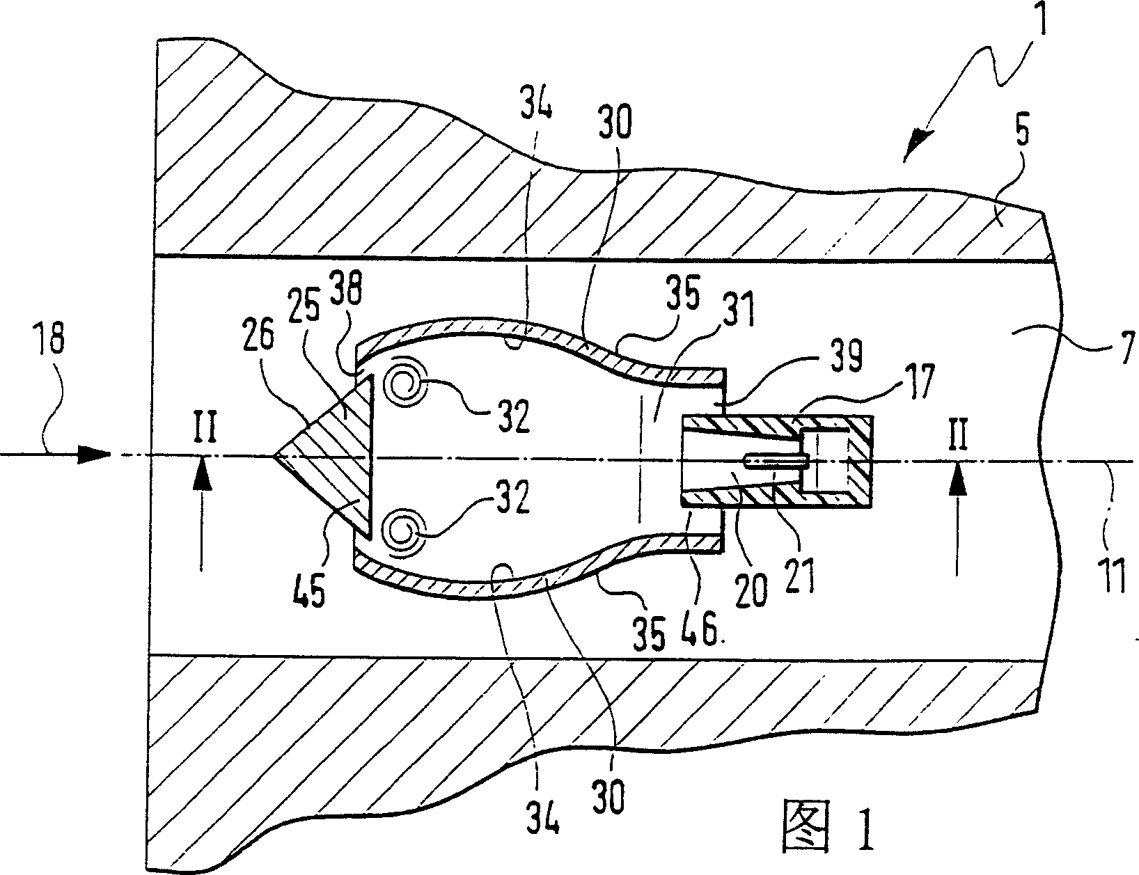
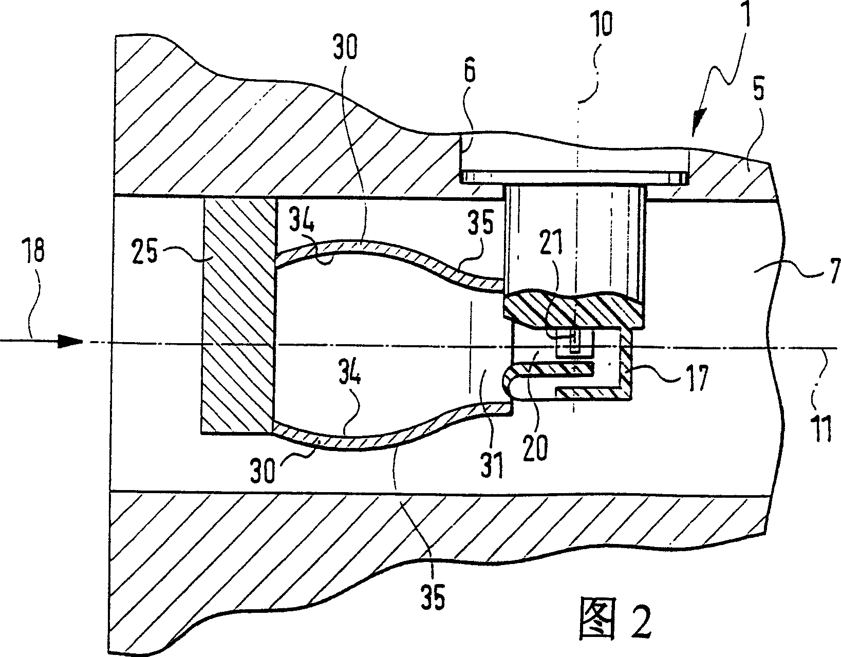
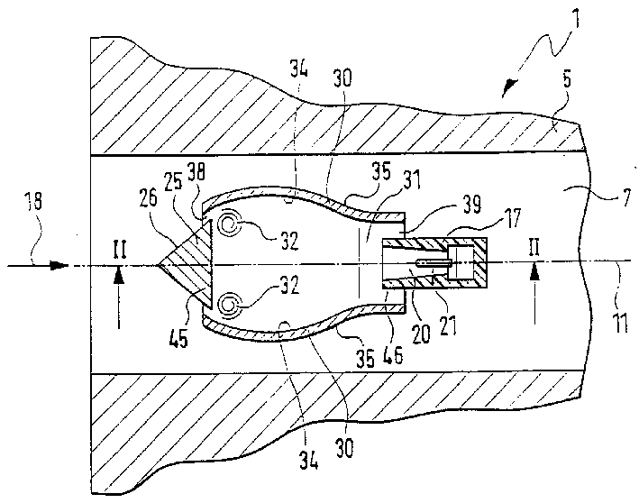
[0020] FIG. 1 shows a cross section through a device designated with 1 for determining at least one parameter of a flow medium, in particular intake air of an internal combustion engine. The internal combustion engine may be a compressed air mixture and forced ignition internal combustion engine, or an air compressed and self-ignited internal combustion engine. As shown in detail in the longitudinal section along the line II-II of FIG. 1 in FIG. 2, the measuring body 17 preferably has a thin, rod-shaped rectangular parallelepiped-shaped configuration extending longitudinally in the direction of the insertion axis 10, Furthermore, it is inserted, for example pluggably, into an opening 6 cut out in the wall 5 of the intake duct 7 , which forms a flow duct. The hatched wall 5 is, for example, part of a cylindrical intake duct 7 through which a medium, in particular air drawn in by the internal combustion engine, flows. The wall 5 of the suction duct 7 delimits a flow section whi...


PUM


Abstract

Known devices for measuring the mass of a flowing medium can be impaired in their measurement precision by fluid components carried along in the medium. The device (1) according to the invention has a ricochet body (25), which is disposed upstream of the measuring element (21) and is at least partially encompassed by an outer ring (30), where the outer ring (30) constitutes a section inside the outer ring (30) that tapers in the flow direction (18) in order to deflect fluid components, which are carried along in the flow (18), away from the measuring element (21) by means of the ricochet body (25). The invention is provided for measuring the mass of a flowing medium, in particular for measuring the intake air mass of internal combustion engines.

Description

technical field [0001] The invention relates to a device for determining at least one parameter of a flow medium. Background technique [0002] Such a device is already known (DE-OS 35 15 206), in which an adsorption element is arranged in the measuring channel of the device in the vicinity of the measuring element in order to avoid accumulation of dirt particles in the air flow on the measuring element. Mounting the adsorption element in the vicinity of the measuring cell creates a wind shadow downstream of the adsorption element, which should prevent dirt particles from accumulating on the measuring cell. However, the liquid components transported together in the air flow can deposit on the measuring cell, which can lead to a detrimental change in the characteristic curve of the device and its measuring accuracy. [0003] EP 0 967 466 A1 discloses a device in which a retarder is used to generate a vortex. However, this results in increased measurement signal noise at the...

Claims


Application Information

Patent Timeline
Patent Type & Authority Patents(China)
IPC IPC(8): G01F1/00F02D35/00G01F1/684G01F15/12G01K13/02G01L19/06G01P5/00
CPCG01F15/12G01F1/6842F02D35/00
Inventor 托马斯·伦津
Owner ROBERT BOSCH GMBH
Why Eureka
Try Eureka