Precision cutting device and splitting method for test sheet

A precision cutting and test piece technology, applied in metal processing, electrical components, semiconductor/solid-state device manufacturing, etc., can solve the problems of increasing the difficulty of section analysis, unsuitable cutting distance, and high price

Inactive Publication Date: 2005-09-07
AU OPTRONICS CORP
View PDF0 Cites 0 Cited by
  • Summary
  • Abstract
  • Description
  • Claims
  • Application Information

AI Technical Summary

Problems solved by technology

But above-mentioned ion beam cutting method must use ion beam generator 20 to produce ion beam 21, and the price of ion beam generator 20 is as high as tens of millions of yuan, and its cutting speed is very slow (about 2~5 μ m per hour), usually with For the formation of cutting marks 13 below several microns, it is not suitable for cutting distances greater than tens of microns
[0004] In addition, if Figure 1A As shown, since the cutting mark 13 on the test piece 10 is cut by the ion beam 21, and the ion beam 21 does not cut the test piece 10, so the electron microscope 30 can only pass through the gap of the cutting mark 13 from the oblique cross section Make observations, and the observation angle is limited within a certain range (less than 52 degrees)
Secondly, since the observation direction of the electron microscope 30 is not perpendicular to the section, a clear image of the layered structure cannot be obtained for the thin film of a specific material in the circuit layer 12, which increases the difficulty of section analysis

Method used


Image

  • Precision cutting device and splitting method for test sheet
  • Precision cutting device and splitting method for test sheet
  • Precision cutting device and splitting method for test sheet

Examples


Embodiment Construction

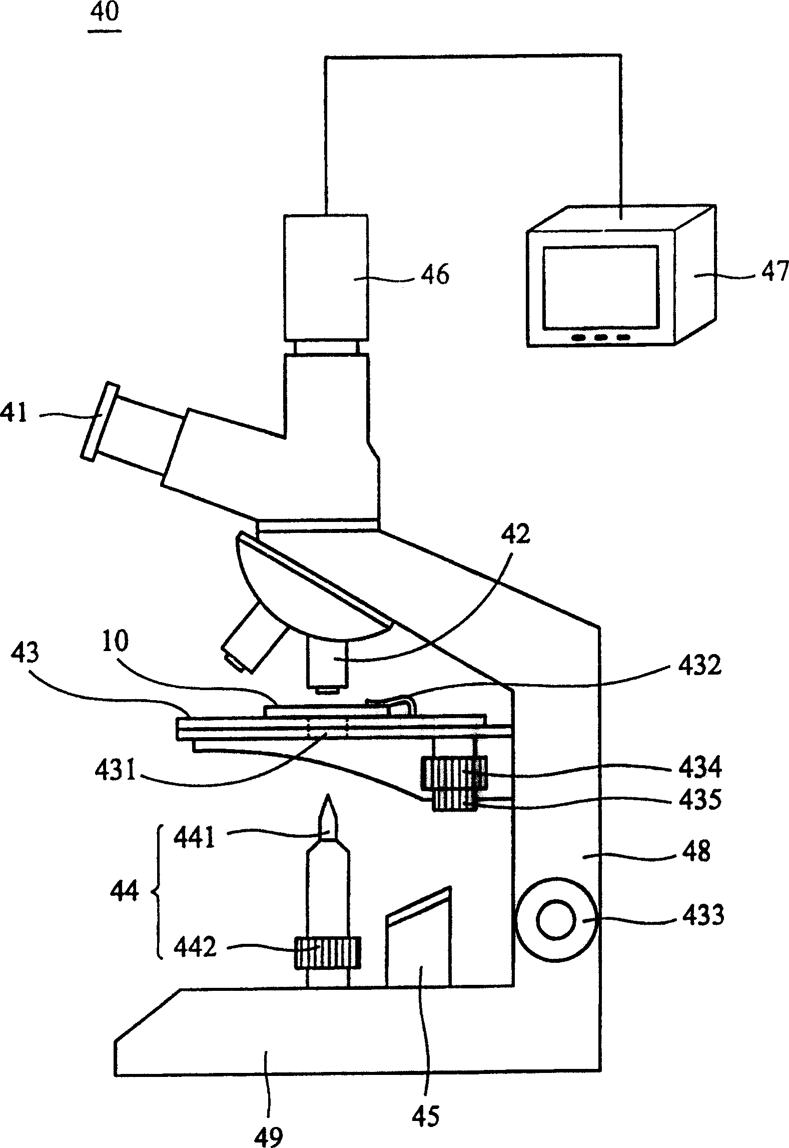
[0023] figure 2 It is a side view of the precision cutting device of the test piece of the present invention. Such as figure 2 As shown, the precision cutting device 40 of the present invention includes a microscope and a cutting tool group 44 that can be vertically telescopic and movable; wherein the optical microscope used in the present invention has a carrying platform 43 that can carry the test piece 10, an adjustable magnification lens group and a bottom light source 45. The carrying platform 43 carrying the test piece 10 is arranged on the support arm 48 of the optical microscope, and the vertical position of the carrying platform 43 can be adjusted by the platform vertical adjustment wheel 433 . The lens group includes an eyepiece 41 and an objective lens 42 , and different magnifications can be selected by adjusting different objective lenses 42 to display the microstructure of the test piece 10 . A bottom light source 45 is arranged on the base 49 below the carr...


PUM


Abstract

The precise sample cutting equipment includes one optical microscope and one cutter. The optical microscope has one movable bearing platform and one lens combination, the bearing platform is for sample to be fixed on and the lens combination is for regulation of enlargement factor of the optical microscope to display the microscopic structure of the plane in the sample to be cut. The cutter is set below the bearing platform and is used to form cutting trace in the sample via the through hole in the bearing platform.

Description

technical field [0001] The invention relates to a device and a splitting method for precisely cutting a test piece by using an optical microscope and a cutting tool. Background technique [0002] In the manufacturing process of various semiconductor components, manufacturing process defects are often formed on semiconductor components due to suspended particles in the air, mechanical aging of equipment, malfunctions, or improper human operation. In order to improve the product qualification rate and effectively control the production cost, a section analysis is usually performed on the defective part to find out the problem. [0003] Figure 1A It is a schematic diagram of the existing cross-sectional analysis by ion beam, Figure 1B for Figure 1A Top view of the pilot strip. Such as Figure 1A , Figure 1B As shown, in the liquid crystal display panel manufacturing plant, the existing cross-sectional analysis method mainly uses an ion beam generator 20 to cut the defect...

Claims


Application Information

Patent Timeline
Patent Type & Authority Patents(China)
IPC IPC(8): B26D3/08B26D5/00B26D5/02H01L21/304
Inventor 黄教忠虞佩信庄玉婷
Owner AU OPTRONICS CORP
Why Eureka
Try Eureka